Basic Techniques (Con’t)
Creating Bulkheads:
Being able to fabricate ‘bulkheads’ is a useful modeling skill and pretty much required when working with vac kits since they often need extra support and rigidity. But, bulkheads are also needed when making up any interior compartments like cockpits, landing gear wells, bomb bays, etc. Many a ‘popped seam’ has resulted from a lack of proper internal support – something that can afflict *any* model kit, vacuform or otherwise.
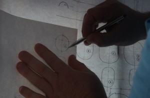
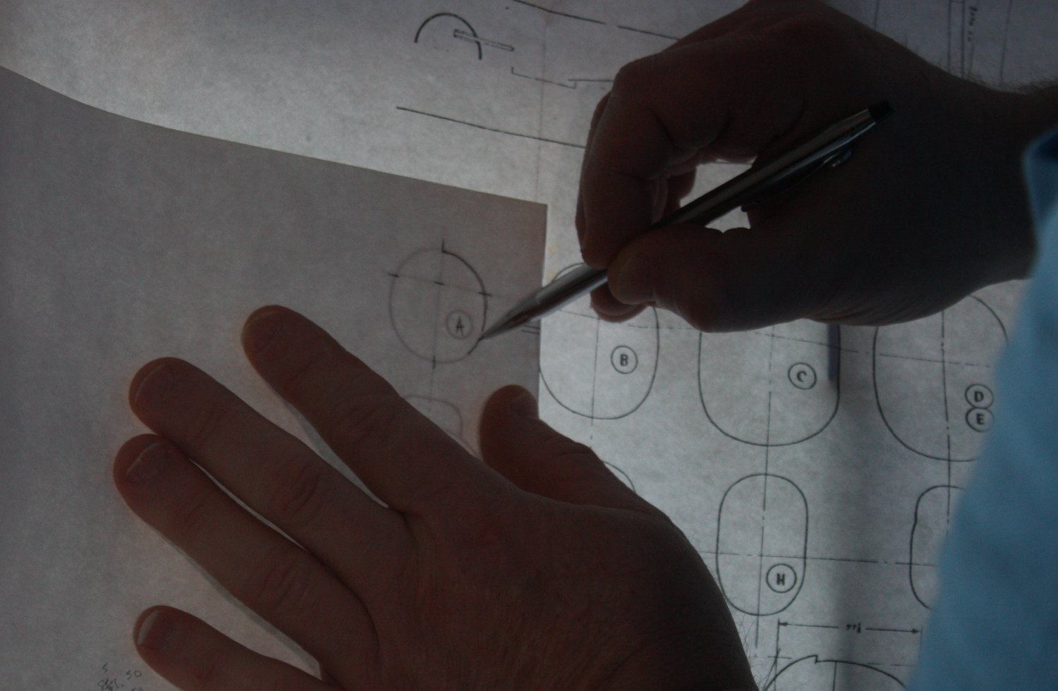
Tracing a pattern using a window as a backlight.
For the purpose of this discussion, the basic material used for bulkheads is sheet styrene plastic. This can be the ‘waste’ backing sheet from a vacuform or sheet from other sources (one common brand being Evergreen.) However, even stiff cardboard can be used to provide support & then further faced with thin plastic sheet & detailed if necessary. Using the same plastic as the main parts simplifies bonding, but dissimilar materials can be used with CA (super-glue) or epoxy adhesives.
There are lots of ways to tackle a bulkhead; the primary challenge being to get a proper profile so there is good contact area with the inside surface. In short, a precisely contoured bulkhead works better & is stronger than an poorly shaped piece, which could also induce unintended distortions. To that end, checking and double checking the shape is best to avoid such problems – and never be afraid to start over.
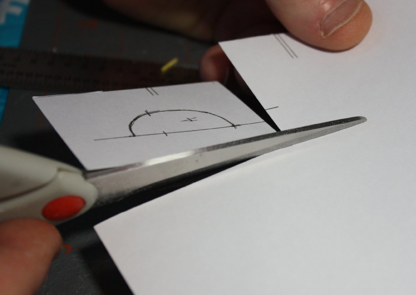
Cutting pattern from cardstock. Note only one half is fully traced.
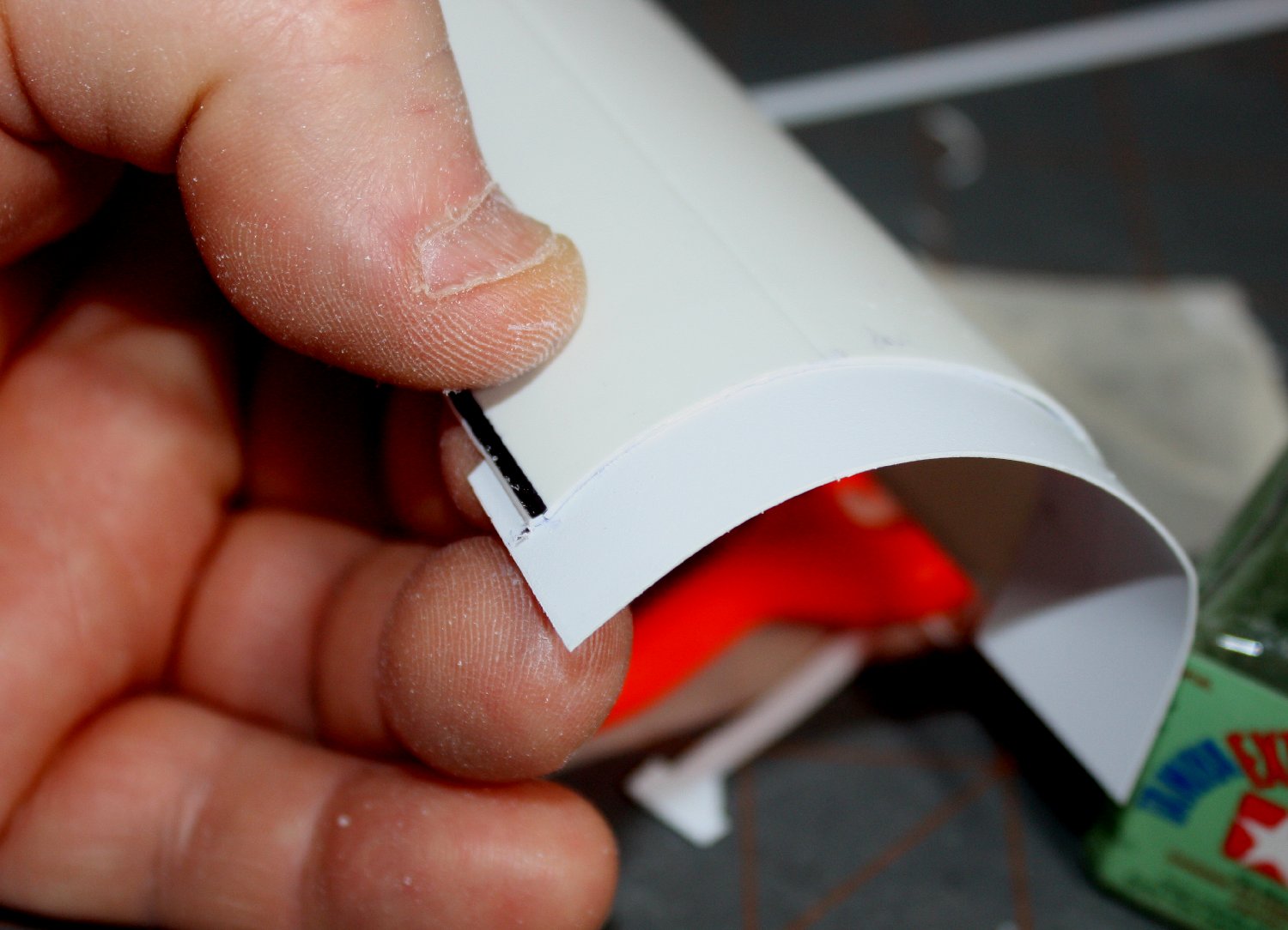
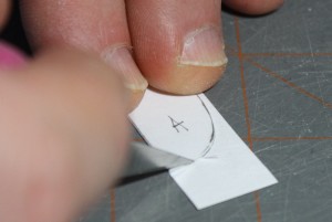
Using a full width mark to aid trimming excess material.
Fabrication starts with a rough pattern. This may be made using a ‘contour gauge’, by ‘trial & error’ or by using the cross sections from a drawing. The rough pattern is made using stiff paper card because it is easy to cut (or even sand) to adjust for a precise fit (plus, it is cheap compared to plastic sheet!) Manila folder paper or similar card stock is ideal but avoid light pressed-paper cardboard (such as ‘cereal box’ material) because it is harder to cut and dulls blades quickly. Once the rough pattern is adjusted for a perfect fit, it can be used as a template to cut the actual bulkhead from the plastic sheet.

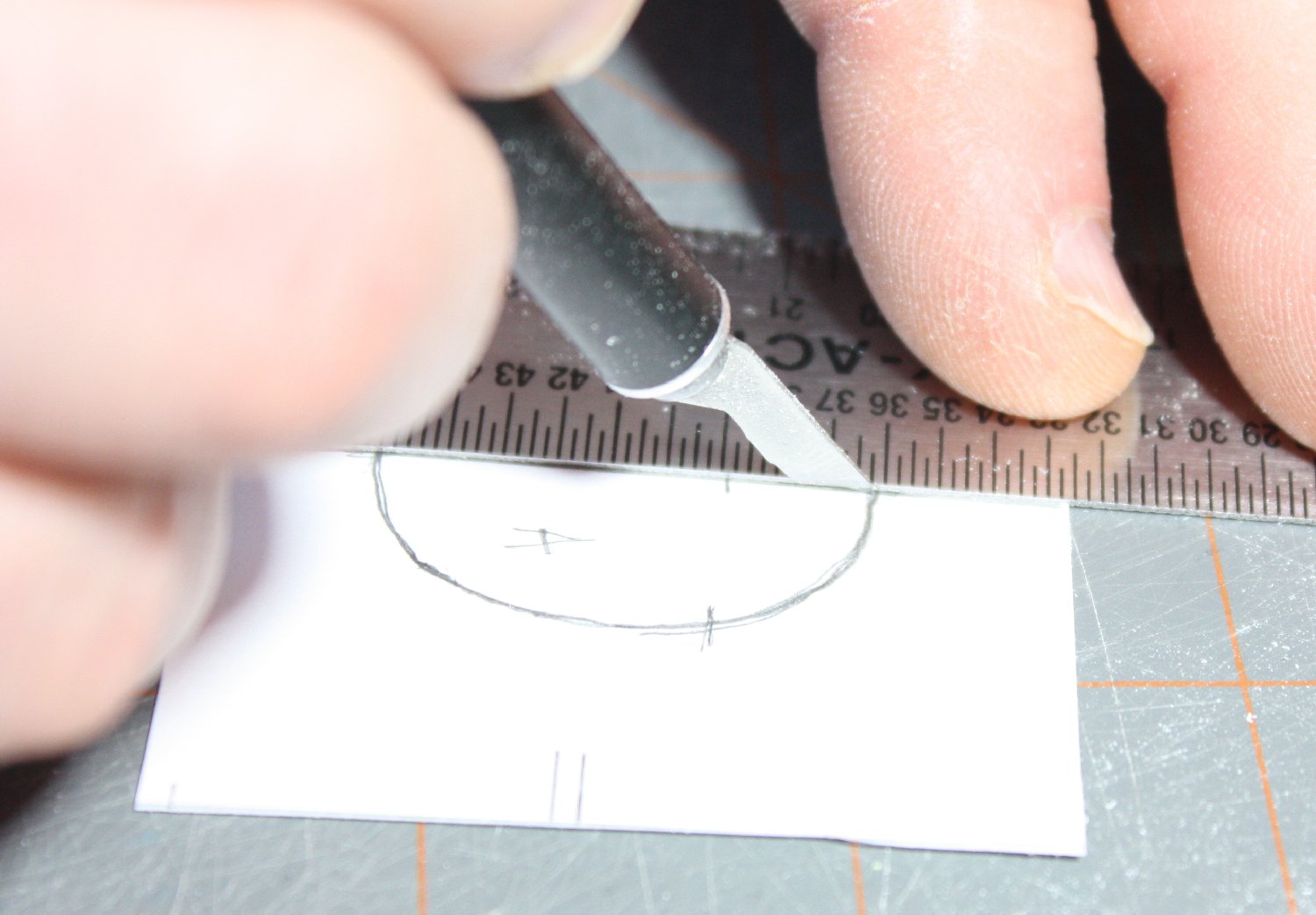
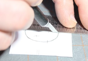
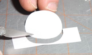
Sometimes a razor makes a cleaner curved cut.
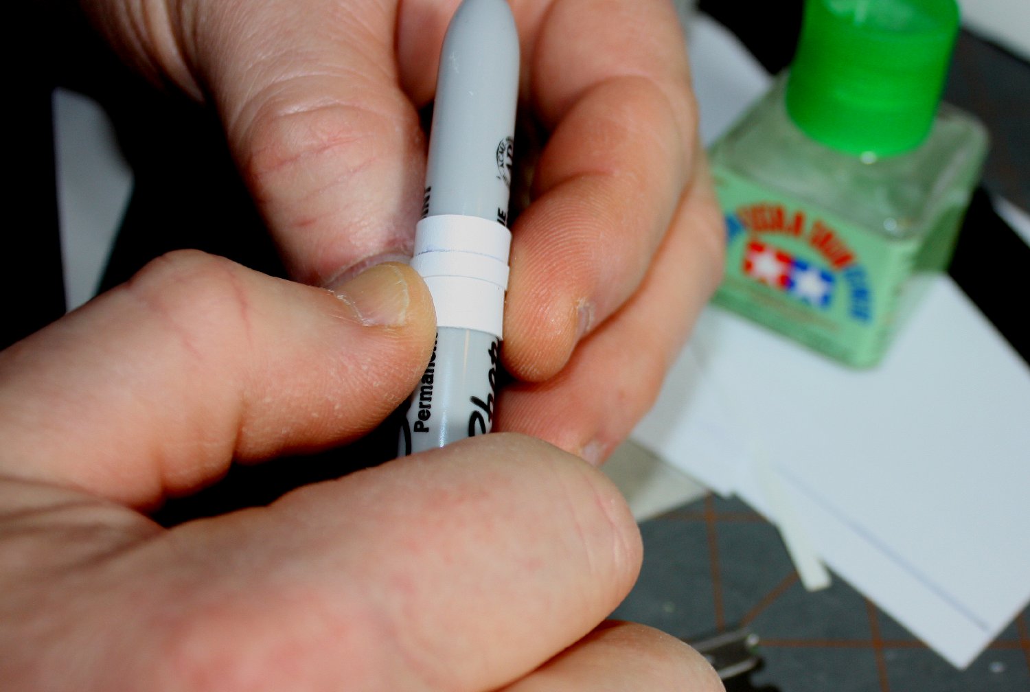
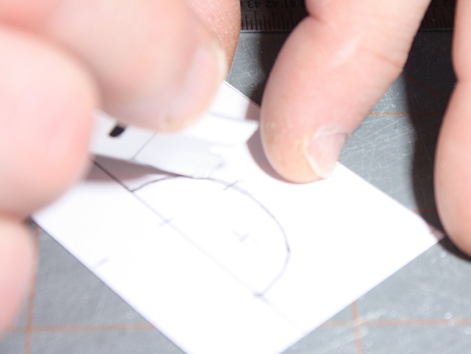
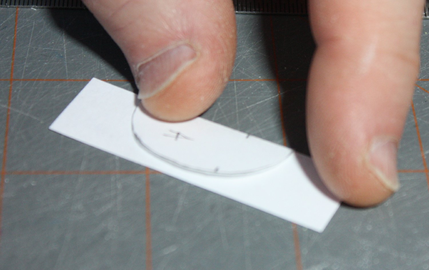
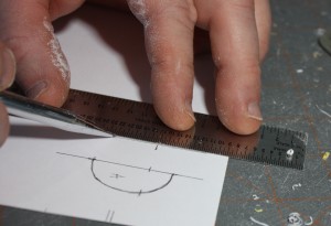
Scoring the center-line to aid folding over.
It is important to avoid distortion where the bulkhead is to go. This is a particular problem with thin- walled vacuform parts, but any part can ‘flex’ when de-molded – even injection molded parts. That is why taking bulkhead ‘measurements’ directly from the parts before removing from the backing is advised. Since a contour gauge requires some stiffness to the part being measured, care is needed to control flex during this process.

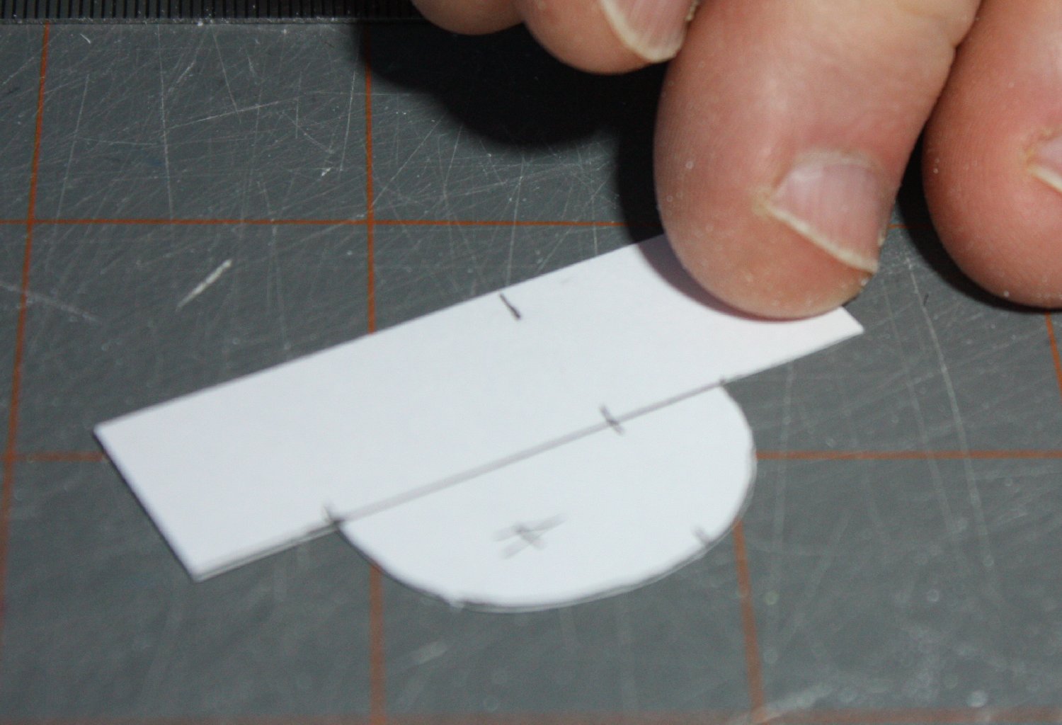
Resulting pattern before duplication of other half.

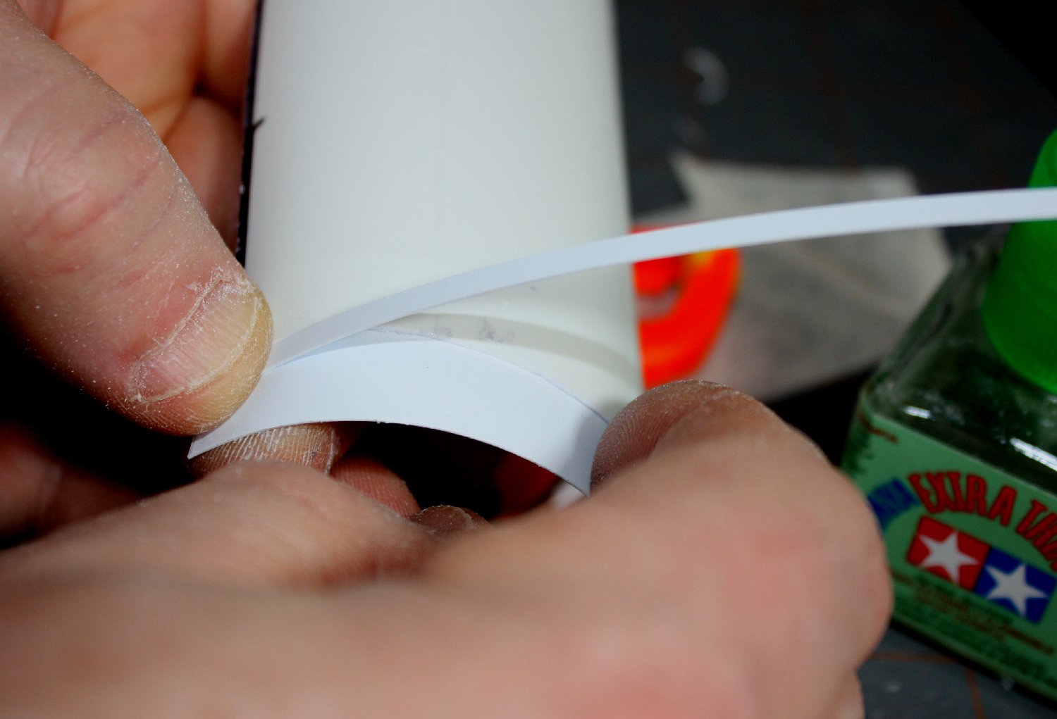
Scored center-line folds precisely over other side.
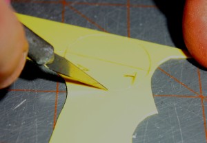
For symmetrical bulkheads typical of fuselages, a ‘center-line (C/L) reference’ should be included on the pattern. For fuselages divided vertically, this would be a vertical line that represents the parting plane of the two halves. To make the pattern symmetrical, make the pattern for one half, then fold it over at the C/L to ‘trace’ out the other half of the bulkhead. Lightly scoring the paper on the center line will make the fold precise. Once cut out, the bulkhead profile should be checked against the shell to ensure a good fit before committing to the sheet plastic.
Cutting profile of other side
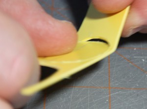
Resulting full pattern is symmetrical
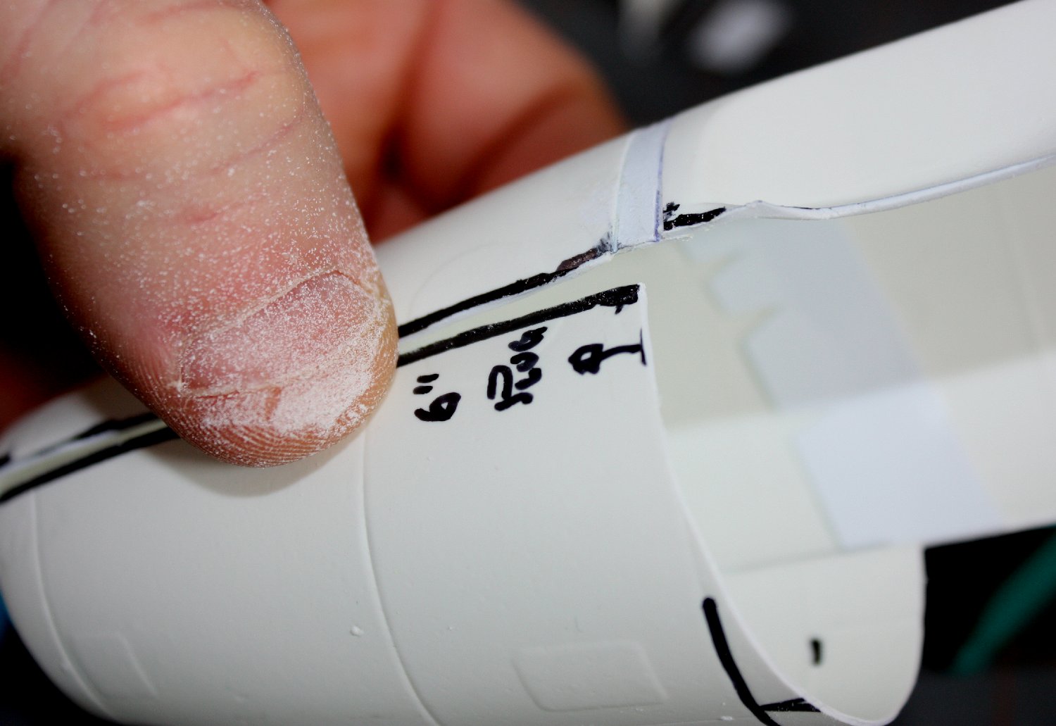
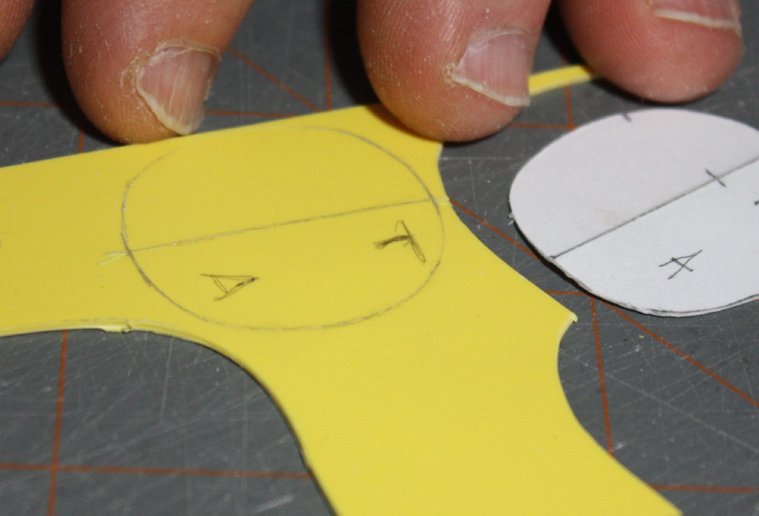
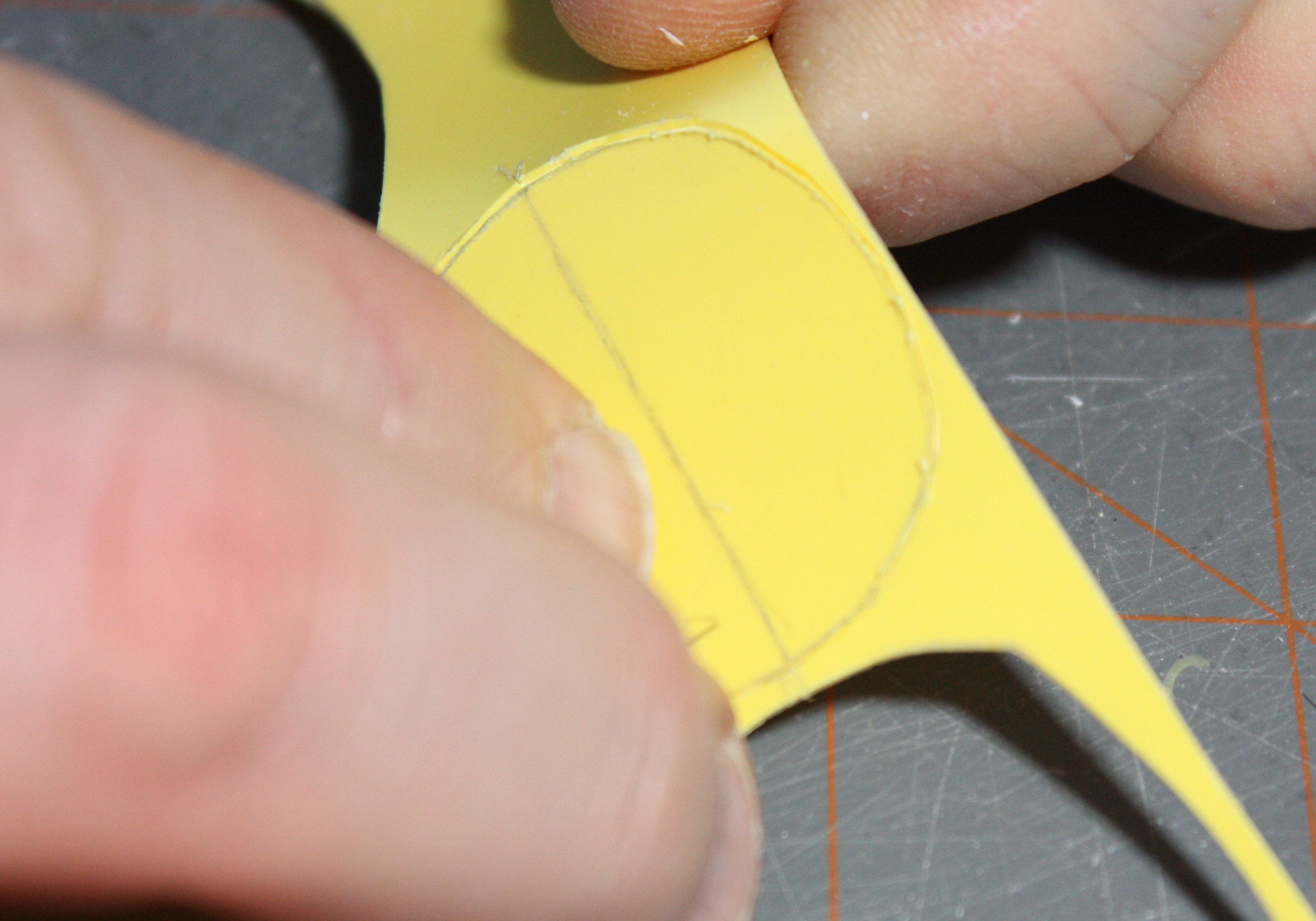
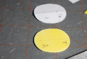
Once the template is finished, then simply trace the shape onto the bulkhead material using a knife or engraving tool, or even a needle in a pin vise. Make sure to include marks to precisely transfer the center line so when the bulkhead is fitted, the it can be aligned with the edges of the fuselage half to achieve proper vertical alignment.

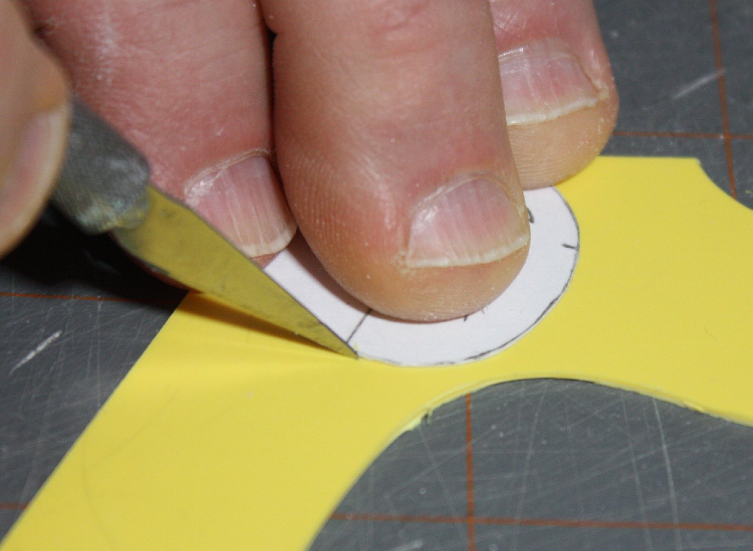
Scoring around paper template making sure there is no shift while cutting

Scored marks are highlighted for visibility
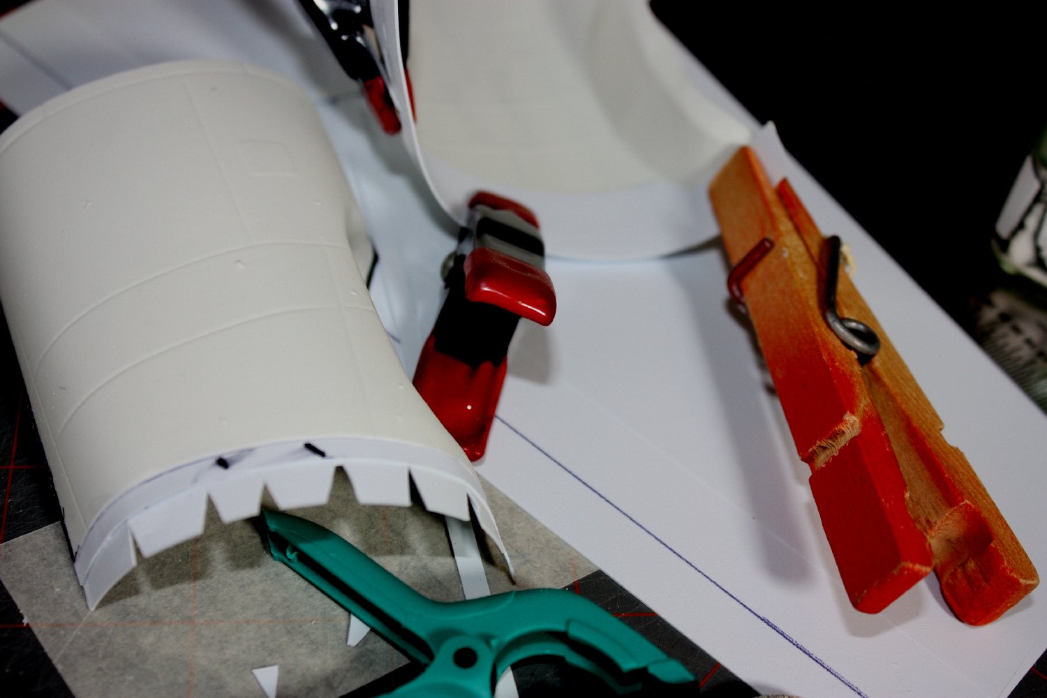
The bulkhead then is usually glued into one half first, using the other half as a brace while the bond cures. Just clamp the halves together with the bulkhead in place, taking care to keep it ‘square’ in all axes while closing (this requires three hands.)
Once the bulkheads are set and the halves separated, consideration must be given to how actual gluing of the final assembly will be achieved. Since access to the interior may be restricted & bulkheads may obstruct others, use of a thicker, slow setting cement such as tube glue or epoxy adhesive may be needed.
Scored marks are highlighted for visibility

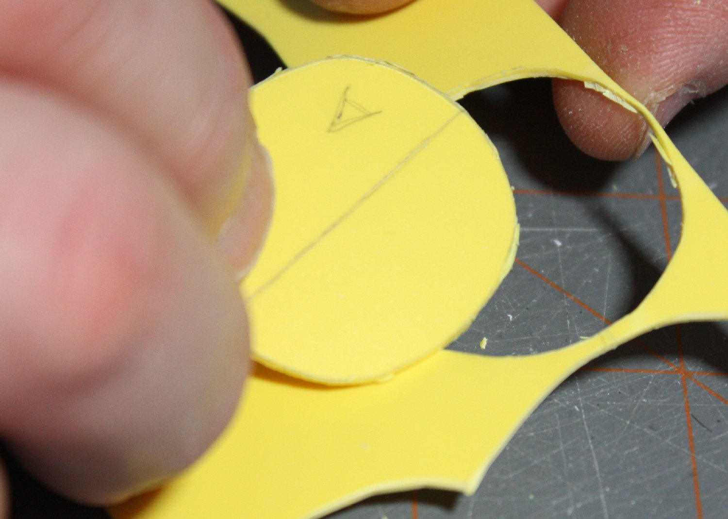
Top of bulkhead & placement ‘code’ applied
Sometimes openings for windows, wheel wells or cockpits may offer access for application of liquid cement. Being imaginative helps solve the problem but sometimes all that is needed is to first prime the joint areas with liquid cement and then apply LC (quickly) at the top & bottom points just before closing the halves completely then turning it on its side so it can run “down” to the mid point will be sufficient.
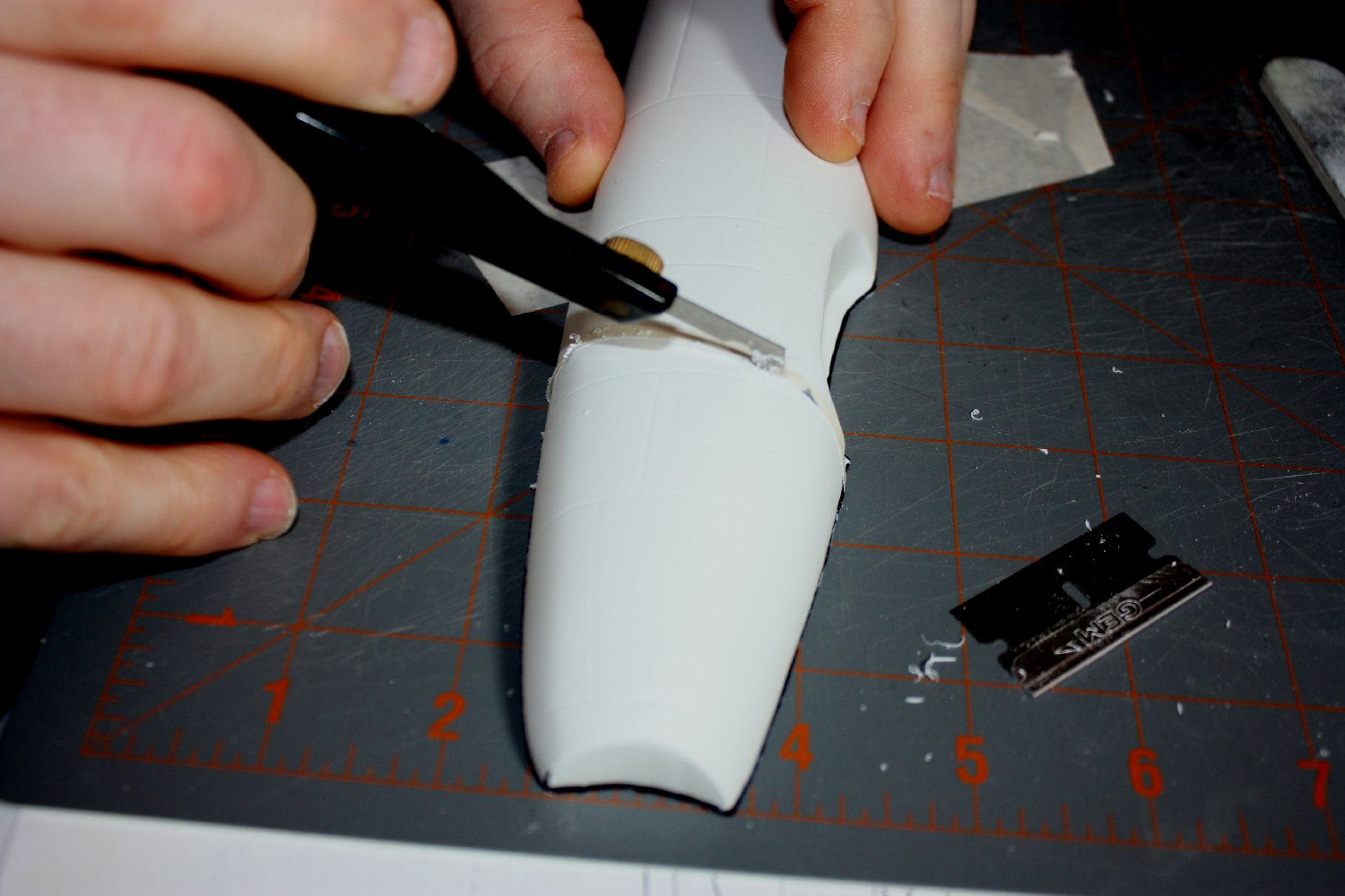
Carefully cutting by repeatedly scoring around the shape

Flexing the score line to break the bulkhead free
A prime consideration when using volatile cements in ‘closed spaces’ is that the glue may distort the plastic at the joints because the glue has no way to “vent” from the interior. This is especially an issue for thin walled vac parts & big assemblies using relatively large volumes of cement . Normally, this avoided by 1) allowing plenty of time for the first gluing to cure before full assembly, and 2) making sure any solid bulkheads have openings cut in them to allow airflow to the interior.
A bit more cutting to help & score begins to ‘snap’

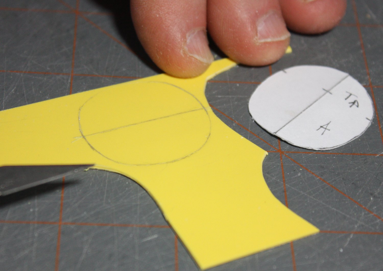
Part removed!
An added advantage is a lighter assembly – helpful when balancing a ‘tail sitter’. Having a small fan blowing on the parts while curing can both help avoid this problem and speed the cure.
Avoiding haste and working as precisely as possible will go far in getting the most from adding internal structural elements to your models – vacuform or not!

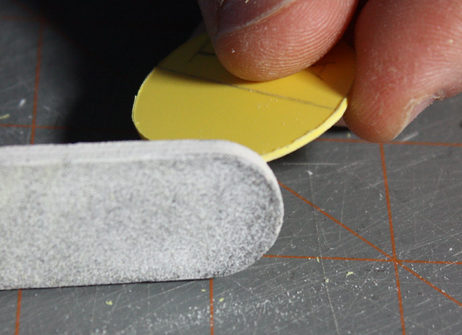
Careful sanding to clean-up the bulkhead
Final result. Paper template can be reused / tweaked as needed.
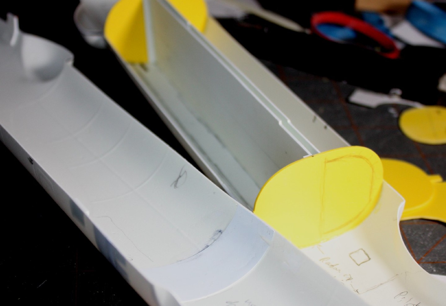
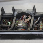
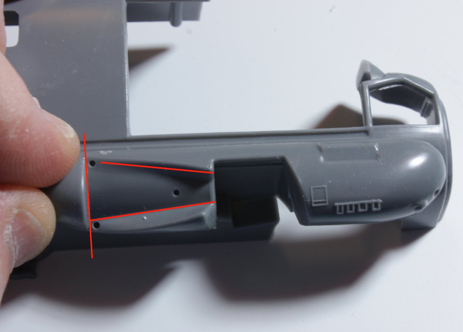
Bomb bay roof flanked by bulkheads; note marking for later bulkhead cut-out.

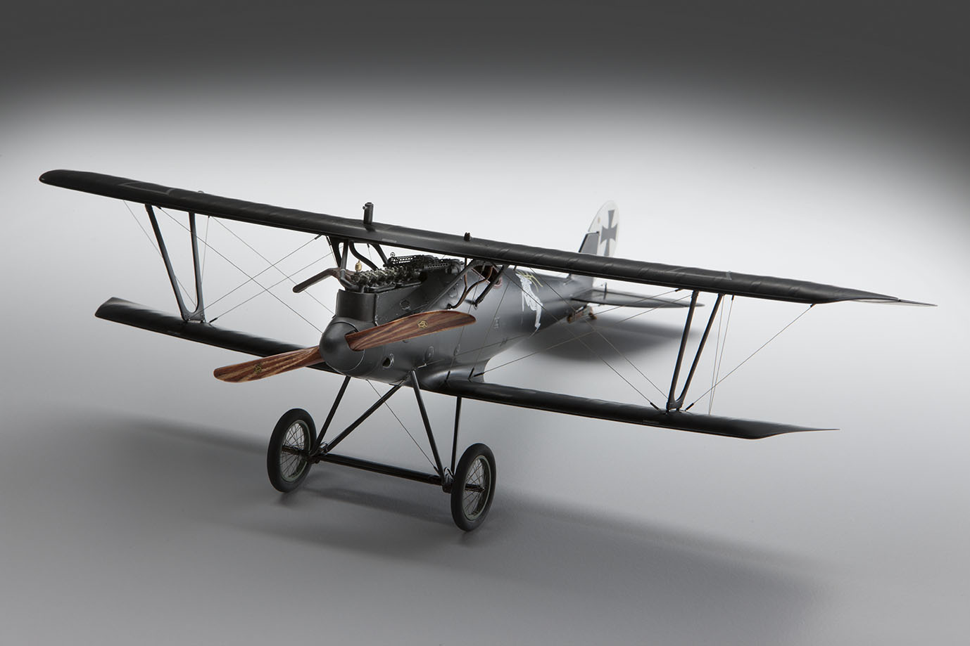
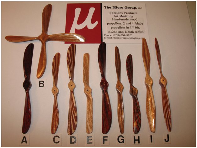
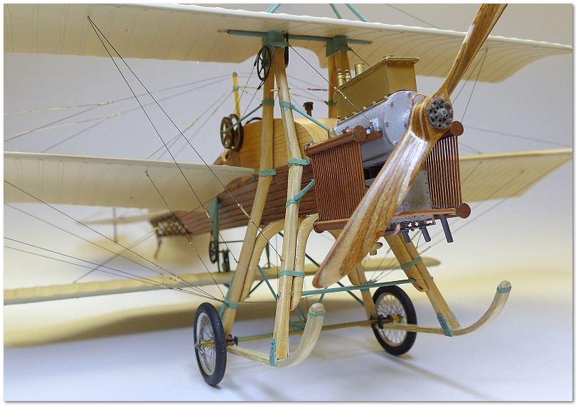 Recently, I read an Aeroscale review of some very high-quality, handmade wooden props produced by ‘The Micro Group, LLC’ company. They looked very impressive and so, being curious, I sent an email inquiry to Craig Rosner, the company proprietor. He sent back some materials showing examples his customers had used and additional specific information. Since his work had previously been unknown to me, I offered to put out some flyers at the National Convention to help ‘spread the word’ as well as posting to the club website. To that end, we’ll have notational ‘business cards’ for distribution, providing contact info and the link to this posting. The advantage is that folks can peruse and download the product information sheet (HERE) at their leisure while not using ‘paper’ to do so.