Challenge: Turn a 1/48 scale P-38 Lightning into an experimental WWII Japanese fighter plane.
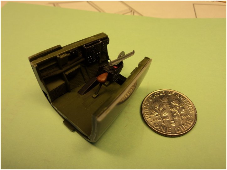
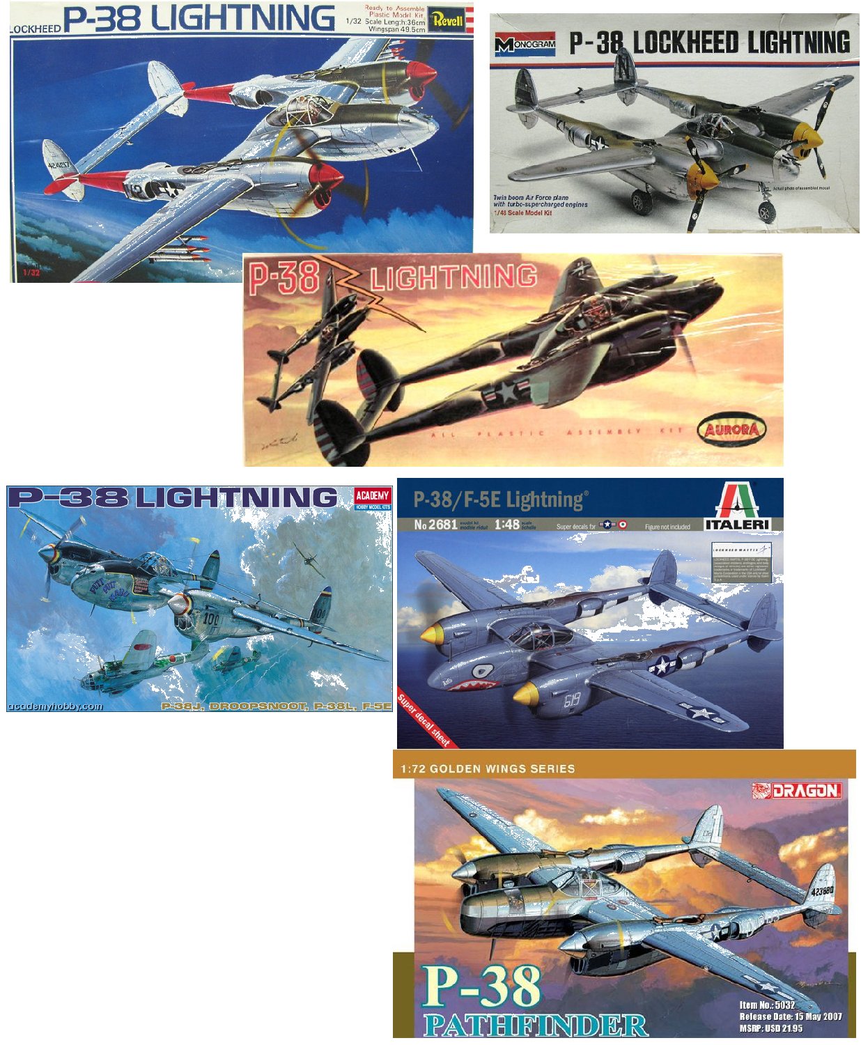
For the November 2014 Club Theme Challenge, we decided to “compete” using any scale or make of P-38 kit, built to any result (in other words, you don’t have to end up with a P-38…) Because the club had been given a sizable donation of model kits by Mr. David Ekker of Chesapeake, VA & he was a big Lightning fan, we figured everyone would already have a suitable kit of some type on hand just by virtue of various raffles, fund raising sales, etc. 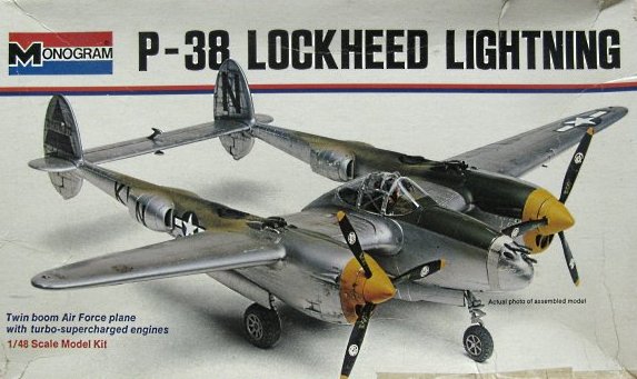 I myself selected a nice vintage Monogram 1:48 scale P-38, kit #6848, for my build, as I wasn’t sure I actually wanted to build a P-38 and hence didn’t want to “waste” a more expensive tooling in case things went very wrong. Also, even if I elected to build it as a ‘straight’ P-38, I still thought it would be cool to see just what I could do with the same kit I’d built as a kid (I still remember the ‘apple green’ paint – mixed from square bottle Testor’s primary colors – I used in the gun bay!)
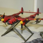
As it turns out, I came across a set of drawings & artwork for the Mansyū Ki-98 while surfing the ‘Web for inspiration. This was an experimental pusher-prop, twin boom fighter/attack aircraft the Japanese were building just before the surrender, after which the aircraft was destroyed to keep it out of US hands. The inspiration was how the vertical tails of the Ki-98 looked identical to the P-38’s – something that was borne out once I’d downloaded & printed 3-view drawings (those survived even if the metal didn’t…) Further comparison with the kit parts showed that I could source most of the tail booms, the horizontal tails, the prop-boss and the wings(!) from the P-38, at the very least. At this point, “the game was afoot”!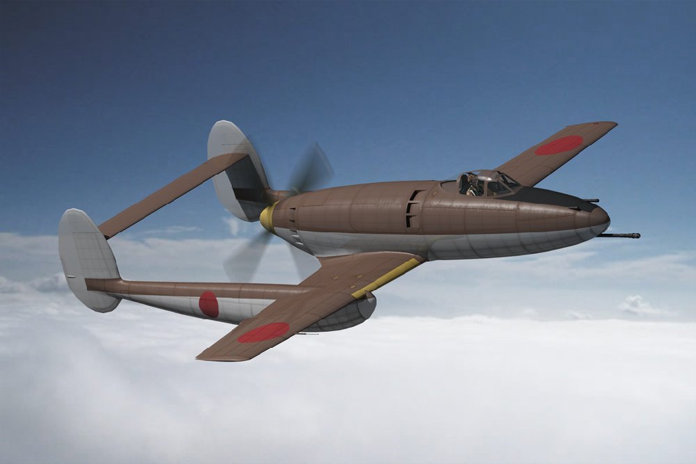
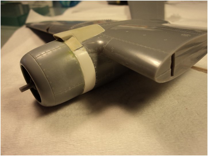
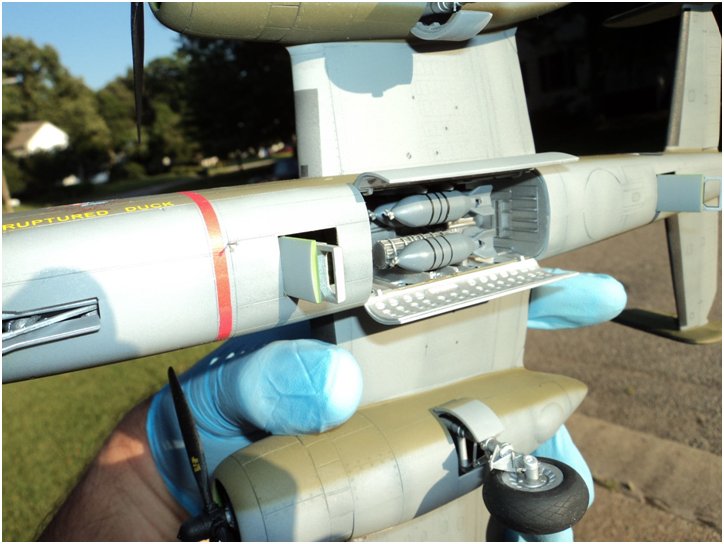
Granted, the P-38 parts were not ‘drop-in’s for the needed components. Surgery was required on every part but most of the work would be fairly basic ‘saw & plug’. The main issue was how to make the fuselage. On the Ki-98, the fuselage was of circular cross-section from stem to stern and contained the guns, cockpit and a ‘buried’ radial engine driving a four-bladed pusher prop (similar to the Kyushu J7W1 ‘Shinden’) via an extended shaft. This mounted atop a tapered wing that had two underside-mounted tail booms which also enclosed the main landing gear. A nose-gear retracted into the underside of the fuselage nose. It featured a concentric array of cooling air intakes and exhaust vents plus an underside mounted turbo-supercharger to adorn the aft fuselage. Overall, lots of interesting features. However, nothing from the P-38 kit really could be used for the fuselage pod. Fortunately, a dig through the ol’ parts bin produced a 1:32 F-4 Phantom center line drop tank (I’m assuming from an old Revell kit) that was almost exactly the right length, width & contour. The ends, which were very ‘pointy’, required chopping off, but one of the P-38 prop ‘hubs’ was a drop-fit at the rear while the other end would require a replacement nose. Overall, a very good start!
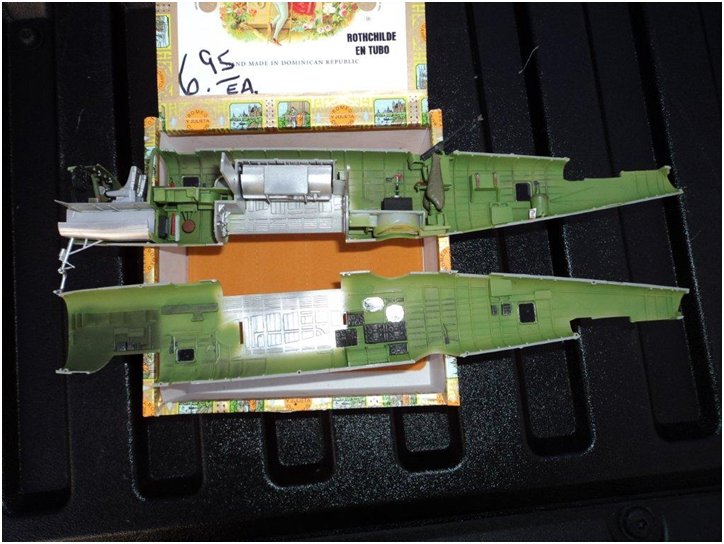
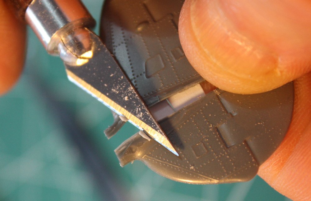
Wings: The kit wings were of similar but not exact taper as the Ki-98. They also incorporated part of the tail booms (top half) & mounting ‘pads’ (bottom) plus the central ‘fuselage’ nacelle halves. I started by scribing cut-lines (using the great UMM-USA scribing tool) either side of these features, following up with a micro saw (also from UMM-USA) to give me four wing pieces per wing half. I envisioned re-assembling all these parts into a one piece wing that the center nacelle would mount upon (as appeared prototypical from the drawings.)
Before proceeding further, I ‘scraped’ the outer wing panels’ trailing edges for thinness. The leading edge was also scraped to reduce the ‘height’, consequently thinning the wing overall. This was done before any ‘surgery’ because it impacted the actual shape of the wing in plan view (though to a relatively minor degree.) The center panel parts could wait as those trailing edges would end up changing due to the large chord difference between inner and outer panels. I also cleaned up any molding defects and alignment pins/sockets from the inside of the wing parts to prevent interfering with later work.
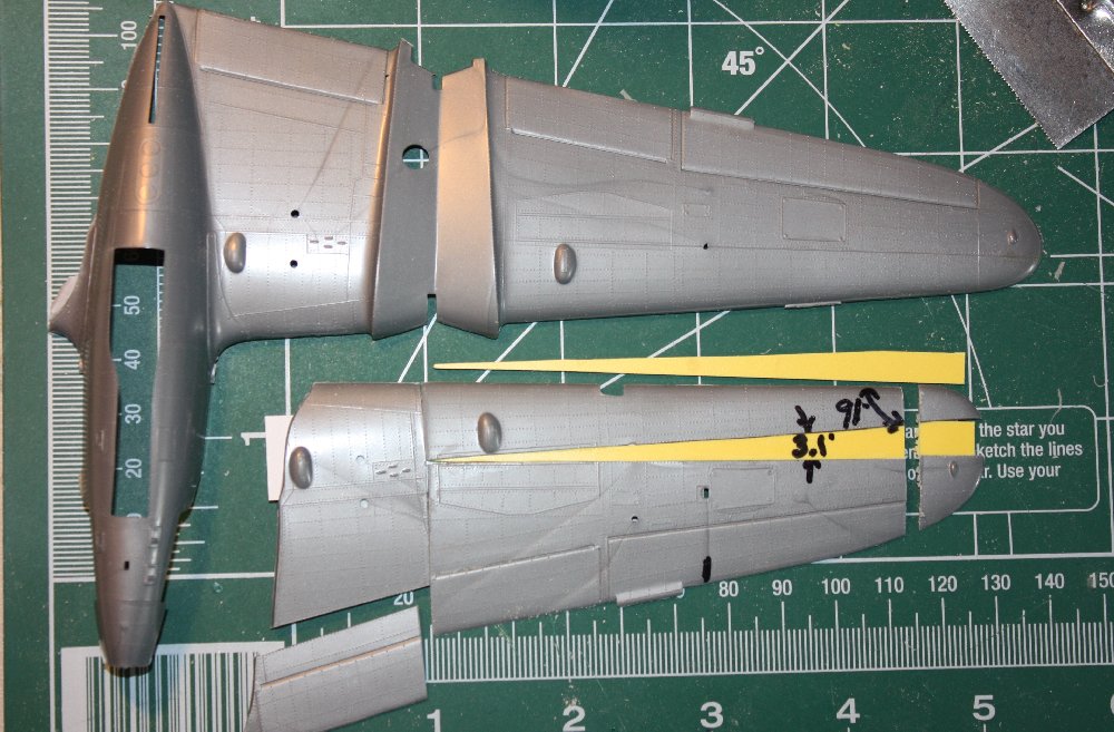
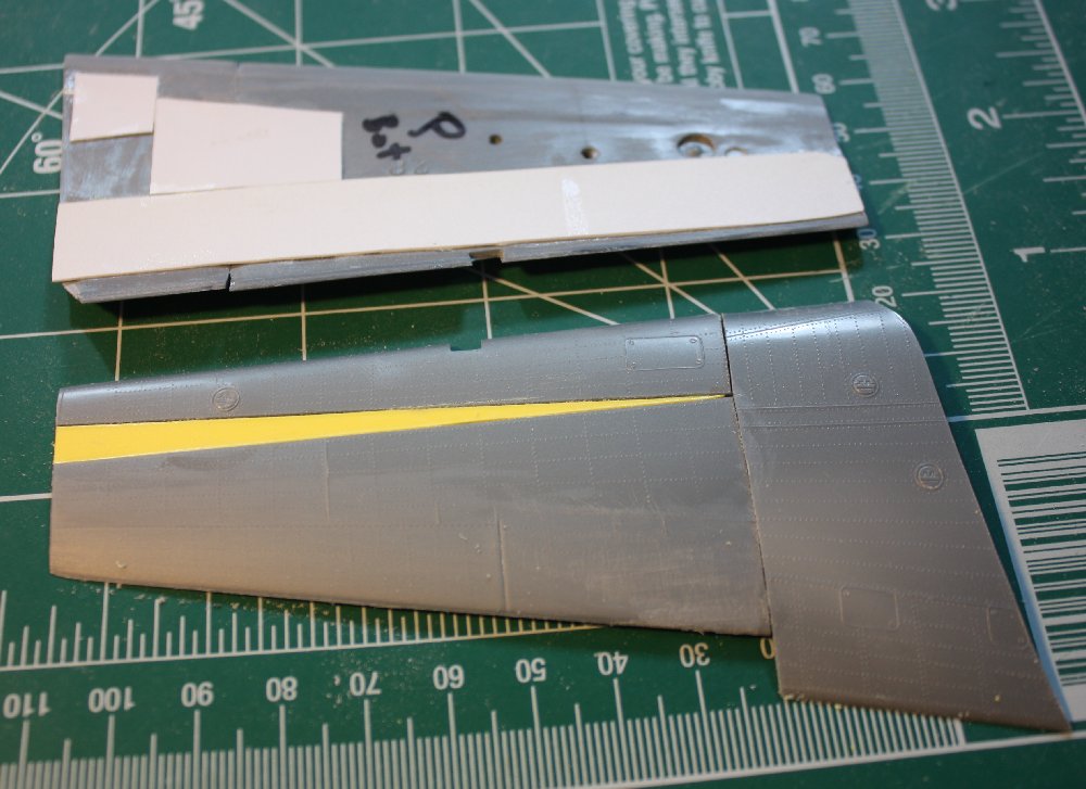
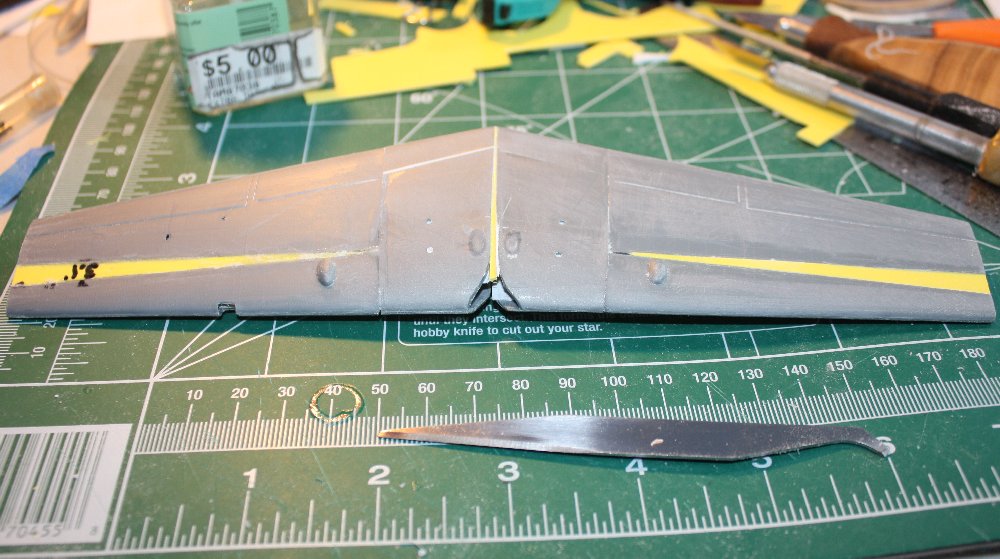
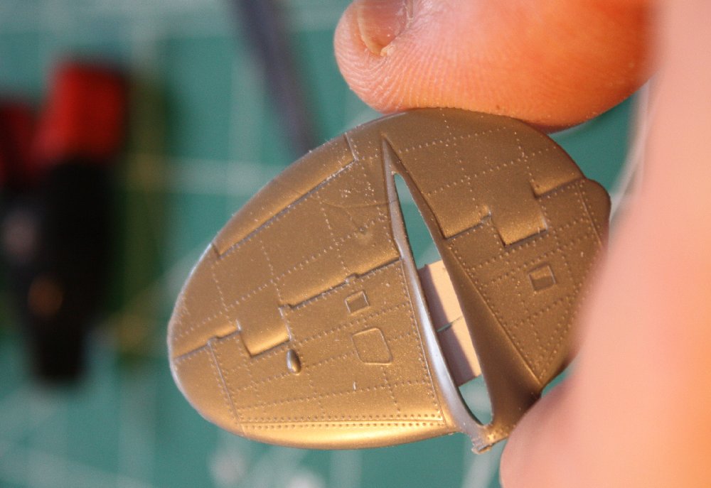
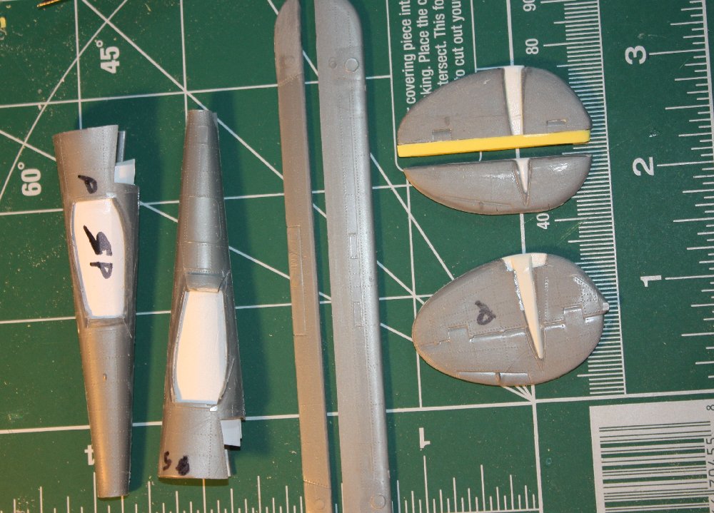
Kit wing bottom before and after ‘chop-chop’
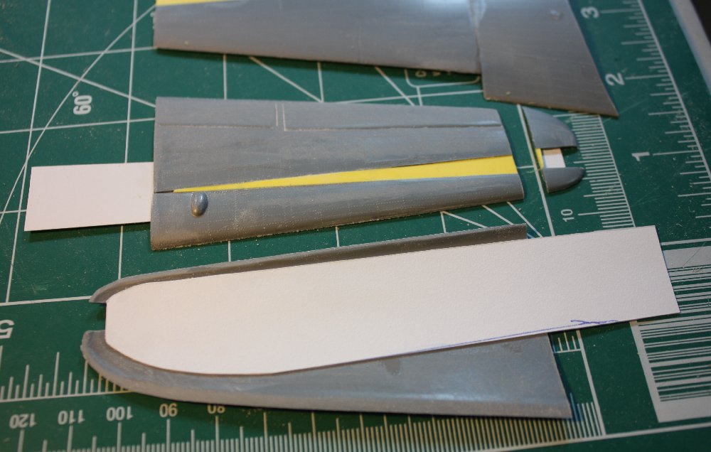
Different stages of wing surgery & re-assembly
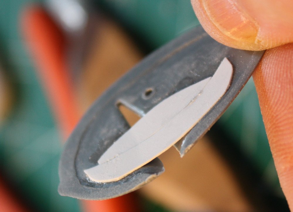
Wing panel wedge & backing sheet
Top wing splice was simplified
Laminating the wing ‘spar’ from plastic sheet
Wing spar installed
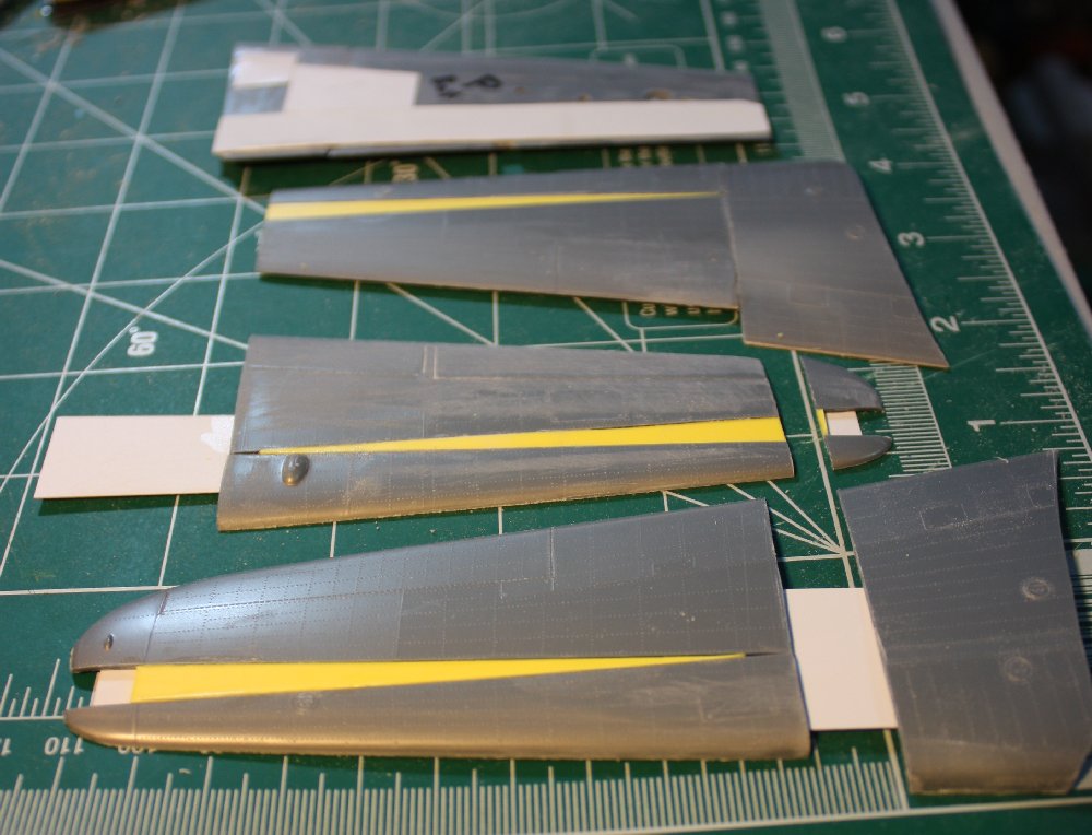
One piece wing assembly underside
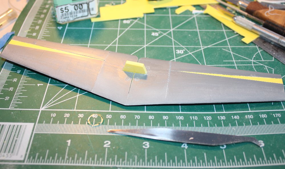
Assembled wing top surface
I started the ‘surgery’ with the lower outer wing, port side. To correct the taper, I sawed the outer panel in half along a transverse panel line (about where a real spar would have been) to give me a front and rear half to the panel. Then, laying the pieces on the drawings (which I had confirmed were essentially a ‘true’ plan view instead of a ‘projection’) at a point where the inboard cut matched the chord, I simply shifted the leading & trailing edges to match while keeping the inboard ‘corners’ in contact (in short, the P-38 wing was narrower at the tip than the Ki-98 wing.) This ‘swing’ separation showed a wedge shaped gap which I marked on the plans and measured the included angle & widest width using a protractor & machinist’s rule. Then, using the length of the long cut and the angle, I marked the spacer wedge onto .040″ thick sheet plastic. By marking an additional parallel to the long dimension, I created a rectangle with a diagonal line connecting opposite corners. This gave me two identical ‘wedges’ to plug the wing corrections on both wings. In essence, the ‘wedges’ established the correction, not an attempted ‘placement’ to establish a gap that would then be filled.
Then, I used .010″ plastic sheet to make long ‘backer strips’ to glue to the inside surfaces of the two panel halves. This would bridge the gap and back the ‘wedge’ plug. These were made long enough to later back the inner panel pieces as well.
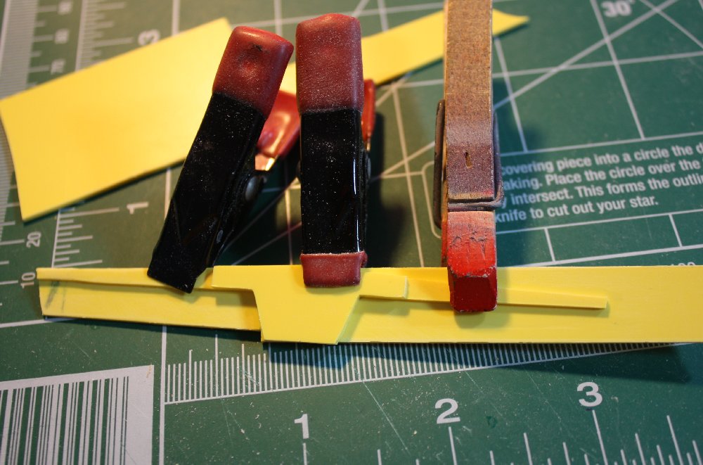
I first glued the strip to the leading edge half, after shaping to match the wing tip contour. Once set, I then placed the wedge onto the backer strip and used that to precisely place the trailing half of the wing panel, applying Tamiya Super Thin cement liberally. Everything was clamped until the glued joint set overnight. This same process was then repeated for the other lower, outer panel (using the first panel to check uniformity), followed by essentially the same process for the upper halves, again using the previously completed panels as check ‘templates’.
With the four outer panels ‘plugged’ to their new taper, the inner panel pieces (originally between the P-38 tail booms and the center nacelle) were then mated with the corresponding outer bits. The inner panels required adjustment for the now ‘kinked’ joint as well as for chord width. Since my backer strips had been made extra long, the inner panels were glued to the strips once the adjustments were finished. Again, ‘checking’ against paired panels helped keep things uniform and symmetrical left & right.
Finally, once all trimming & tweaking was done, sanding and scraping of the trailing edges was finished in preparation of gluing the top & bottom panels together. Before gluing, however, the same method of making a ‘prototype’ panel & then copying to the others was used to trim the wing tips. The Ki-98 had square wing tips, which had already been allowed for when setting the wing chord & taper correction, so it was simply a matter of mark and saw to remove the rounded tips.
This was done using plenty of clamps applied as close to the edges as possible. I wanted the leading and trailing edge joints to be well glued to prevent separation when I later ‘sharpened’ those edges by scraping and sanding.
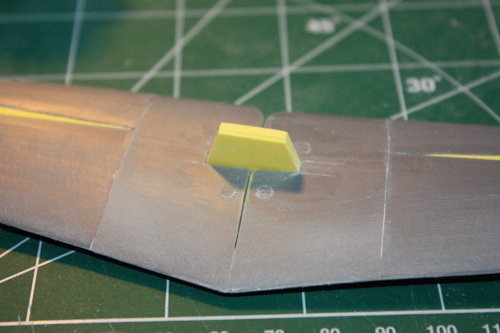
Wing “Spar”: Laminated from .040″ sheet and slid into the wing cavity between the top & bottom halves, the wing spar would set the dihedral, serve as the primary joint between wing halves and act as the mounting fixture for the wing to the fuselage. As such, it was very important that it be sturdy & symmetrical.
I measured the dihedral angles from the plans using the bottom wing line as the angle. I assumed that the bottom wing thickness was basically uniform so the outer surfaces would follow the same angles. I then adjusted the spar height through a bit of trial & error to ensure a tight fit when the spar was slid into each assembled wing half. Essentially, by progressive sanding & test fitting, I was able to establish the needed dimensions and the correct placement of the slot I had to cut into the upper wing to accommodate the spar assembly.
Once I had the correct configuration, I laminated an additional two layers of plastic to the sized spar as reinforcement. This required a further bit of fettling to match the wing interior contours, resulting in a very tight fit. This was then glued into one wing half, clamped and, once set, was followed by the other wing half.
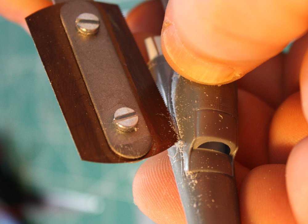
Scribing initial ‘cut’ groove using tip of saw
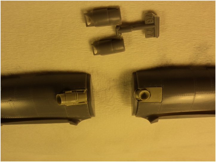
Tail Booms: The P-38 tail booms fitted the drawings in side profile almost exactly – but were too wide in plan (aka ‘top’) view and continued to widen going forward to mate to the P-38 engine nacelles. To begin, I first cut the ‘radiator scoops’ from the sides. This left gaping holes that were then backed with .010″ sheet to support future filling & reinforce the now weakened parts. Then I removed the vertical tail surfaces (required because the Ki-98 tails mounted higher on the booms) & the forward ‘engine’ nacelle sections. This left just the rear section of the tail boom parts, which were then checked for the excess width.
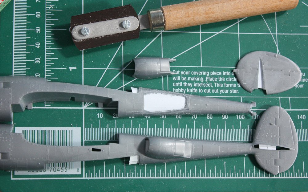
Illustration of the cooler removal (shows backing plastic sheet already fitted before cutting)
This determined the width difference wasn’t uniform along the length as the Ki-98 booms were simply less tapered than the P-38 parts.
To correct the taper, a ‘wedge’ of material had to be removed from the top & bottom of each halves’ edges, being widest at the front & tapering to a point aft. This had to be done the same on each of the boom assemblies to again preserve symmetry. So a staged ‘surgery’ sequence was used, similar to that used on the wings.

Sawing off excess boom width “wedge” (note ‘P’ for ‘port’ labels)
First, one outer boom half was adjusted to the correct taper by scribing & sawing off the excess and then ‘dressing’ the new mating edges so they were square. This was then checked against the plans. Satisfied, I then held the opposite outer boom part against the ‘adjusted’ part and marked so to remove the same amount of material. The result was two identical but mirrored parts. Then the inner boom halves were subjected to the same procedure, starting by sizing one with it’s outer ‘mate’, then using the result to size the “mirror” part. As the inner & outer halves required differing degrees of correction, working with the parts as mirrored pairs maintained symmetry.
Next! Working on the tail…
To Part 2…>

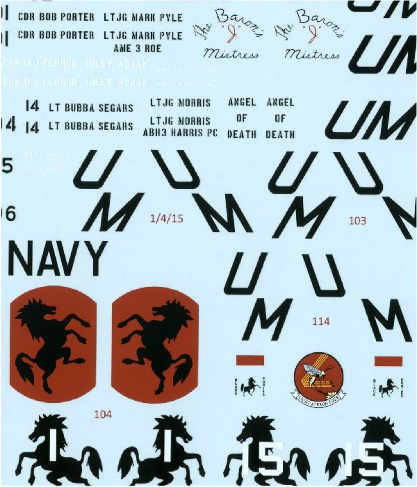 Looking at the “Black Ponies” two-sheet set (one just for the stencils), it has mostly USN VAL-4 birds in green & gray schemes, or overall grey with the colorful VAL-4 ‘rearing mustang’ black horse on a red field unit markings. Also included are a couple from VS-41 ‘Shamrocks’, which acted as the type conversion unit. One VS-41 option is a striking overall black scheme. Plus, one VMO-6 ‘Cherry Six’ USMC bird in green, grey & white scheme. Besides stencils & national markings for one a/c, the individual aircraft numbers and crew names plus any unique markings are all present along with the variations of the propeller, grab-hold & E-seat warnings specific to each aircraft depicted. Plus some helmet markings & sharkmouths for centerline tanks/ guns. Well-researched & with high-quality printing (by Cartograph) of some unique options, the result is an excellent product. Only (admittedly) minor critique being the lack of more USMC choices (somewhat better on the 1:72 sheet with one more of white service markings & ‘Puddy Tat’ artwork) & some difficulty decoding the tiny crew names on the printed profile artwork. I did determine that the crew names are grouped on the decal sheet itself with the associated a/c numbers, so this is easily dealt with once you realize this feature.
 The instructions do include two charts: one providing the variations in the prop, E-seat & hand-hold stencils for each aircraft and second an external loads matrix representative of VAL-4 ops. Mention is made of a unique, non-standard centerline 20mm cannon gun pod however no picture or drawing of this is provided. Steve did email me a picture of the pod when I inquired but more research is required if you want to mount one on your model. Fascinating stuff!
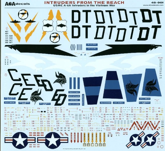 Included is information on ‘converting’ the HobbyBoss A-6 kit to the correct configuration for the markings options provided, followed by very specific data on nearly every airframe flown by the three squadrons covered (VMA(AW)-225/242/533) including the various minor & not so minor differences.
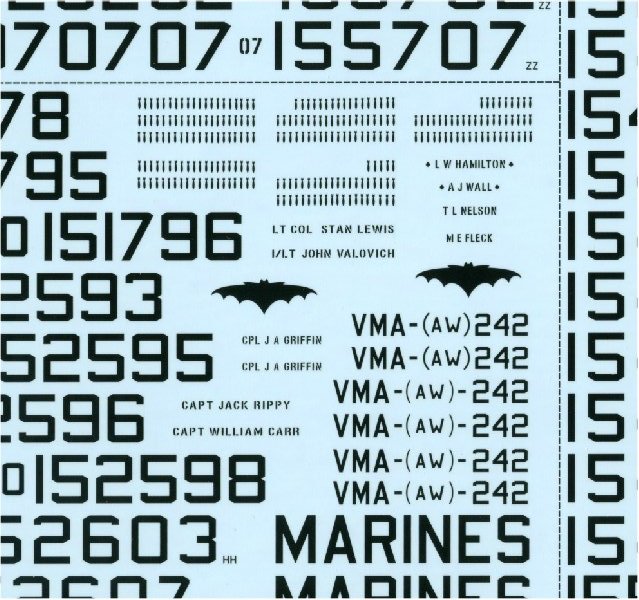


 II fame. What the builder makes of their kits is up to them so several decidedly ‘non-airplane’ results are expected to be on show. There is no restriction of which ‘P-38’ kit is used, other than it has to be of a Lightning (instead of the other possible ‘P-38’ subjects…) Hopefully, such a ‘loose’ structure will fan the creative flames.

