
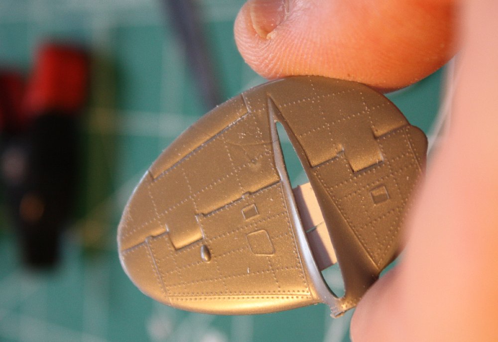
Outer tail half with backer applied *before* cutting off the tail booms keeps proper shape
Tail Surfaces: After cutting apart the P-38 kit’s tail booms, I was left with four vertical tail surface halves, each with good sized gaps to be filled, both from the opening for the horizontal tail and from the trimmed boom connections.
Contoured backing ‘plate’ of .010″ plastic sheet applied to inside of part.
Trimming the tail boom stubs & leveling the horizontal tail “root fairings”.
These parts I had treated similarly to the wings by applying thin, interior ‘backing plates’ to bridge the gaps and maintain the shape before cutting the tails from the ‘boom portion.

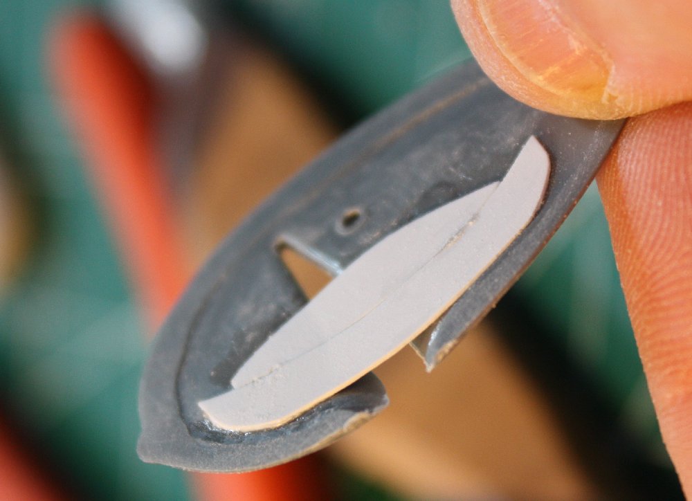
Inner & outer tail halves with backing sheet applied; note different shapes required

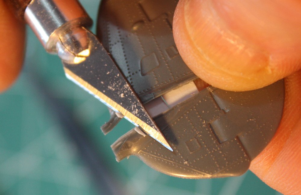
Snapping free a ‘filler’ wedge of 0.40″ plastic
These bits of 0.010″ plastic sheet had to be sized to keep the correct tail thickness when the halves were joined. (The shapes were determined by trial & error.)
Then I added shaped wedges of thicker sheet to fill the gaps up to the outer surface. The initial triangle shape was ‘eyeballed’ and scored on 0.040″ plastic & then ‘snapped’ free. Then needed fine tuning was done by scraping with the hobby knife. Once the wedge fit to my satisfaction, it was glued into the gap. Applications of CA & micro balloons followed by glazing putty would eventually smooth the repairs.

Gluing in the shaped ‘filler’ wedges using clamps
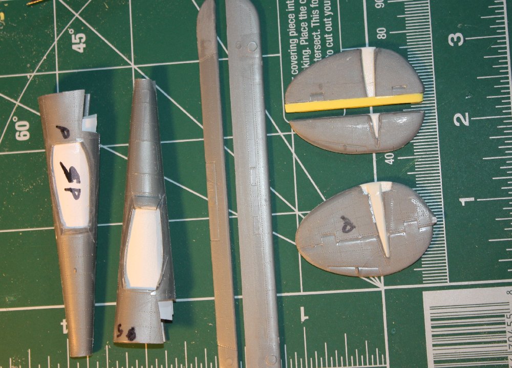
Essential breakdown of tail boom and tail parts after initial surgery & repairs; note the yellow vertical fin ‘plug’.
With the gaps repaired, the rudders needed to be cut off the fins so a chord extension plug could be applied to widen the vertical tails. First, the vertical tail halves were glued & clamped together. Then the rudder was cut off at the ‘hinge line’ molded in the parts using a scribing tool followed by the razor saw. The saw was held at an angle so to give a 45-degree cut, creating a bevel on the rudder leading edge. (This reduces the amount of repair needed to form a proper rounded LE.)
The vertical fin plug was made of three strips of basically equal width 0.040″ plastic, layered three deep. The center strip was staggered a bit ‘forward’ so it could ‘socket’ into the gap left from removing the rudder. This made a ‘C’ channel that, when glued to the ‘rudder post’ of the vertical fin gave a ‘socket’ for the rudder to seat into – just like the real thing. The plug joint & the P-38 hinge ‘horn balances’ were then filled in with CA for strength (the new Ki-98 hinge horn cut-out & shaping was delayed until after final shaping & smoothing was done.) A rat-tail file was finally used to thin & shape the edges of the rudder ‘socket’.
Compared to the vertical tail parts, the horizontal tail modifications were simple. The horizontal tail & elevator on the Ki-98 are narrower and not as long as the P-38 so it was a simple matter of removing excess material. I began reducing the chord by cutting apart the elevator & fin, then used another straight score again to remove extra chord from each ‘half’ as needed. Since the exact length of the horizontal surfaces would be determined once the wing and tail booms plus vertical tails were joined, cutting the horizontal tails would have to wait until that assembly was completed. Using a rat-tail file, a seating groove was filed into the fin while the elevator leading edge was rounded off to match.
<Back to Part 1