Vacuform Aircraft Modeling – Part 4
avatar

Basic Techniques (Con’t)

My basic method of removing parts from the ‘backing sheet’ is outlined below.  However, there are actually some things you want to do prior to removing the parts, if you follow best practices.  These would include:

  • Washing of the parts (just as with an injection molded kit) with a degreasing detergent (dishwashing soap) to remove any surface contaminants.
  • Taking off needed bulkhead cross-sections pre-removal to capture the “true” part sections while the pieces are still constrained by the backing sheet (see below discussion.)
  • Surveying the parts for defects such as sunken surfaces, poorly molded edges and asymmetry (again, while the parts are in their ‘true’ shape.)  I usually will mark any problems areas directly on the part with a pencil.
  • Check clear parts – This involves checking the general fit agreement between the clear pieces and their mating parts.  This is especially important with some ‘classic format’ vac kits that may have been mastered with less than perfect precision.  Obviously, the time to find out problems with clear parts is NOT after the fuselage has been assembled, detailed, painted, etc.  Often, such problems can be best identified prior to removing the ‘opaque’ parts from the backing sheet.

In short, do the usual preliminary work applicable to any model project.  But, back to:

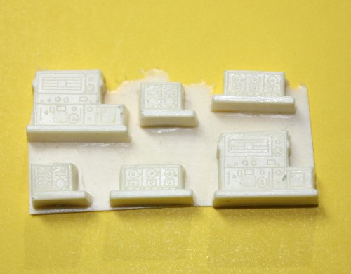
Removing the Parts:  Parts removal begins by outlining the part on the sheet with a fine tipped, (my preference) Sharpie brand permanent marker.  Parts_removal 0
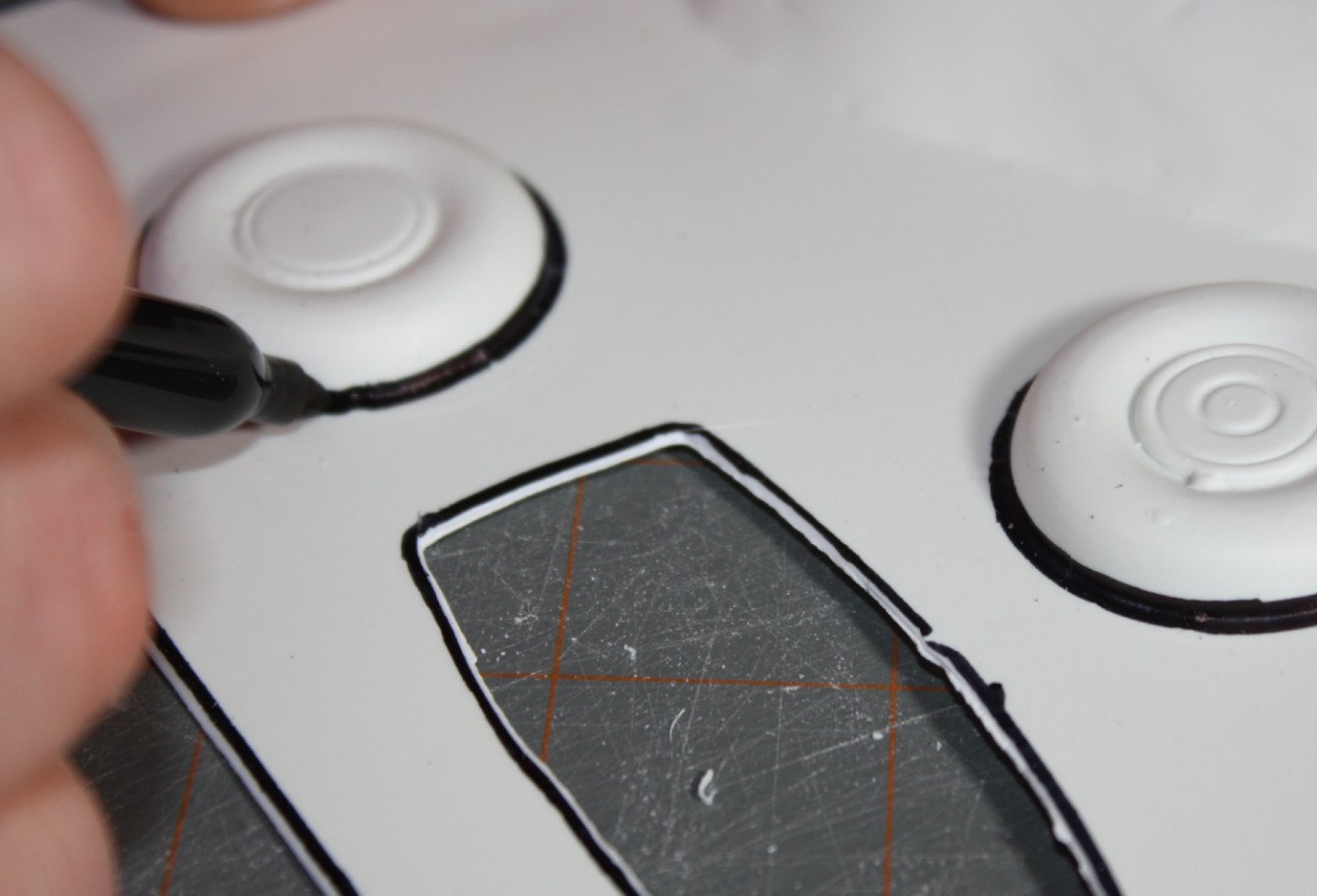
Hold the marker at 45 degrees so the ink gets on both the part and the backing sheet.  This ink mark will serve to gauge the ‘as molded’ edge to the part.  Avoid blunting the marker’s point, so the ink gets fully into the corner between the part & the sheet.  It is important that the mark doesn’t have any gaps. Parts_removal 0A Parts_removal 1

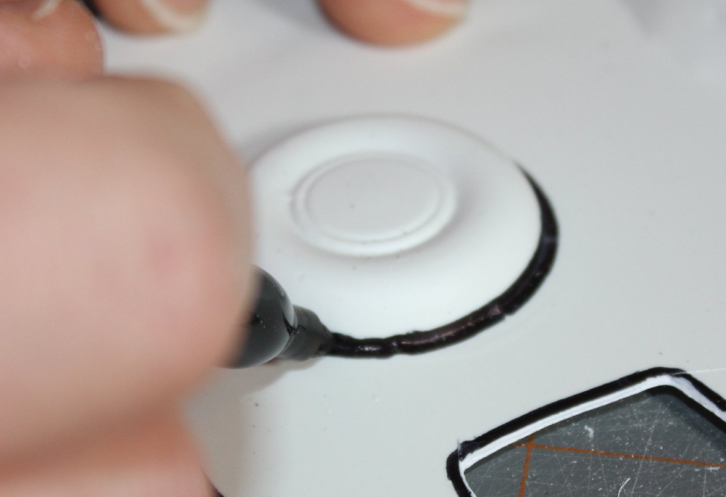
(One alternative I’ve seen others use to establish the parts ‘trim line’ is to give the entire sheet a coat of primer.  This has some advantages for the parts, but as I like to use the waste backing sheet as raw scratch-building material, the primer would interfere with gluing, so I don’t use this method.)

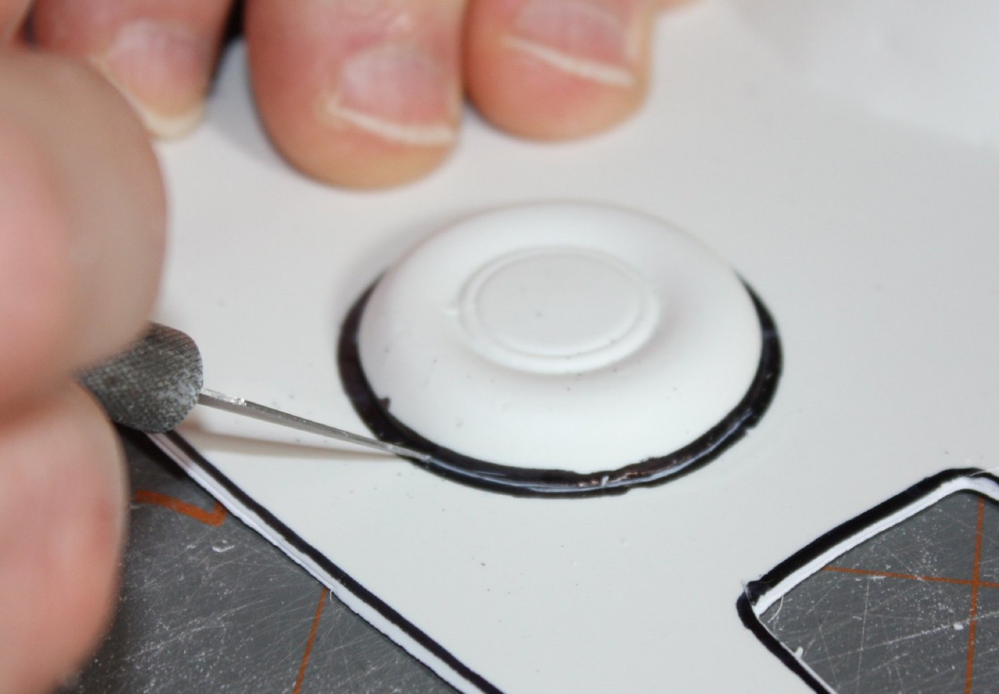
Next, using an appropriate tool (#11 Xacto blade, engraving tool, etc.), score around the edge of the part where it meets the backing sheet.  Score at a 45 degree angle, Parts_removal 1A
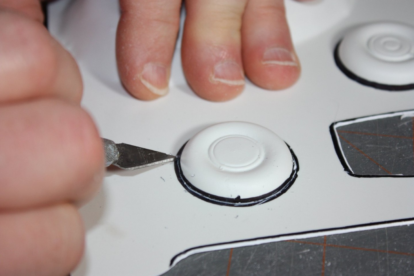
taking care to score lightly using multiple, short passes so to follow the part edge precisely.  Do not attempt to cut through the backing sheet – that is not the goal.  However, tight corners or small radius curves may need deeper scoring to prevent “tearing”.  Do not leave a border of excess backing sheet – that just makes for more work.  Parts_removal 2
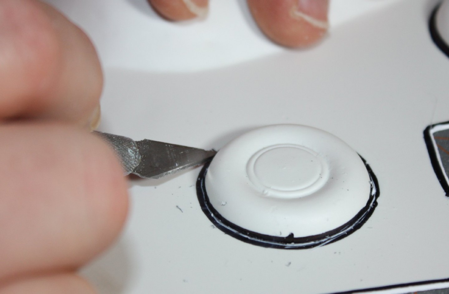
For areas that will eventually be removed such as cut-outs for wings or cockpit openings, leave the molded-in excess to help maintain the part’s rigidity during removal & cleanup.

Although practice will dictate just how much scoring is required, once done, the part is flexed “against the score” (pushed from the side opposite the score which opensParts_removal 3 
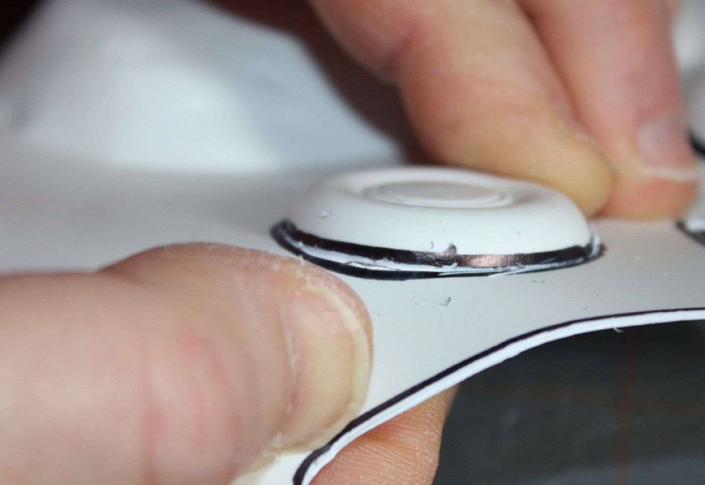
the scored groove wider & stresses the plastic so it fails, or ‘snaps’, in line with the groove.)  Depending on the shape, the score may need to be worked back and forth; it shouldn’t take much effort, so if it does, additional scoring is needed. Parts_removal 4 
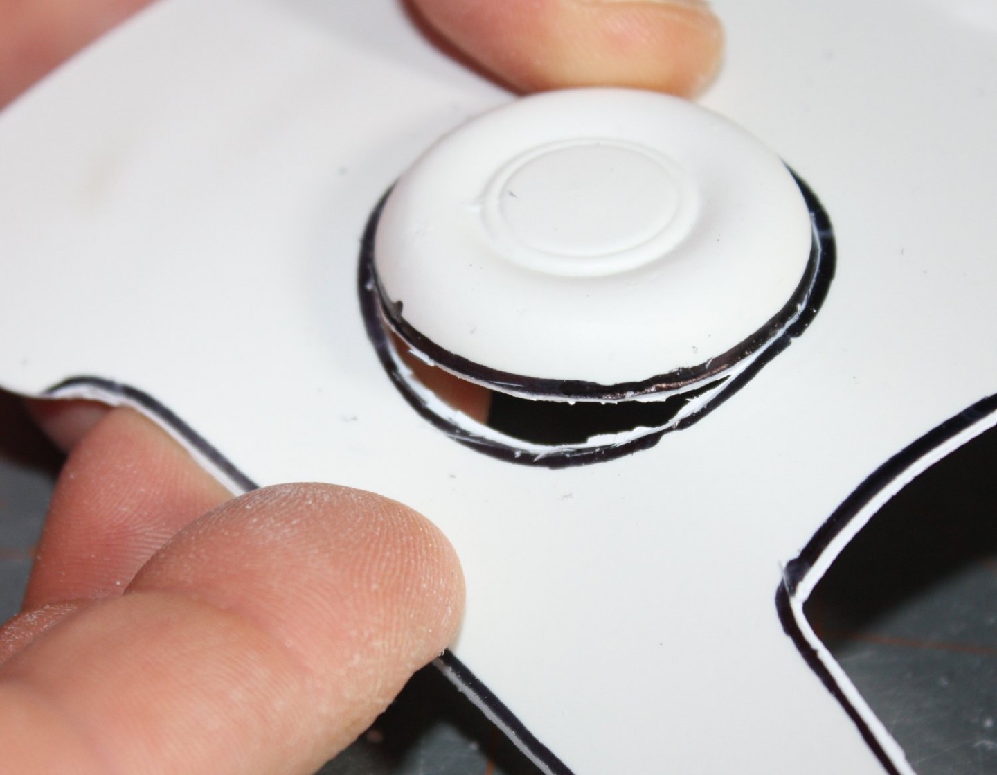
Take special care when dealing with ‘inside corners’ to prevent tearing the break across the part itself.  I usually attempt to cut completely through tight spots just to keep the break along the desired ‘path’.

Once the parts are free of the backing sheet, I usually do a rough ‘dry fit’ of adjoining pieces to get a feel for how things go together.  Parts_removal 5
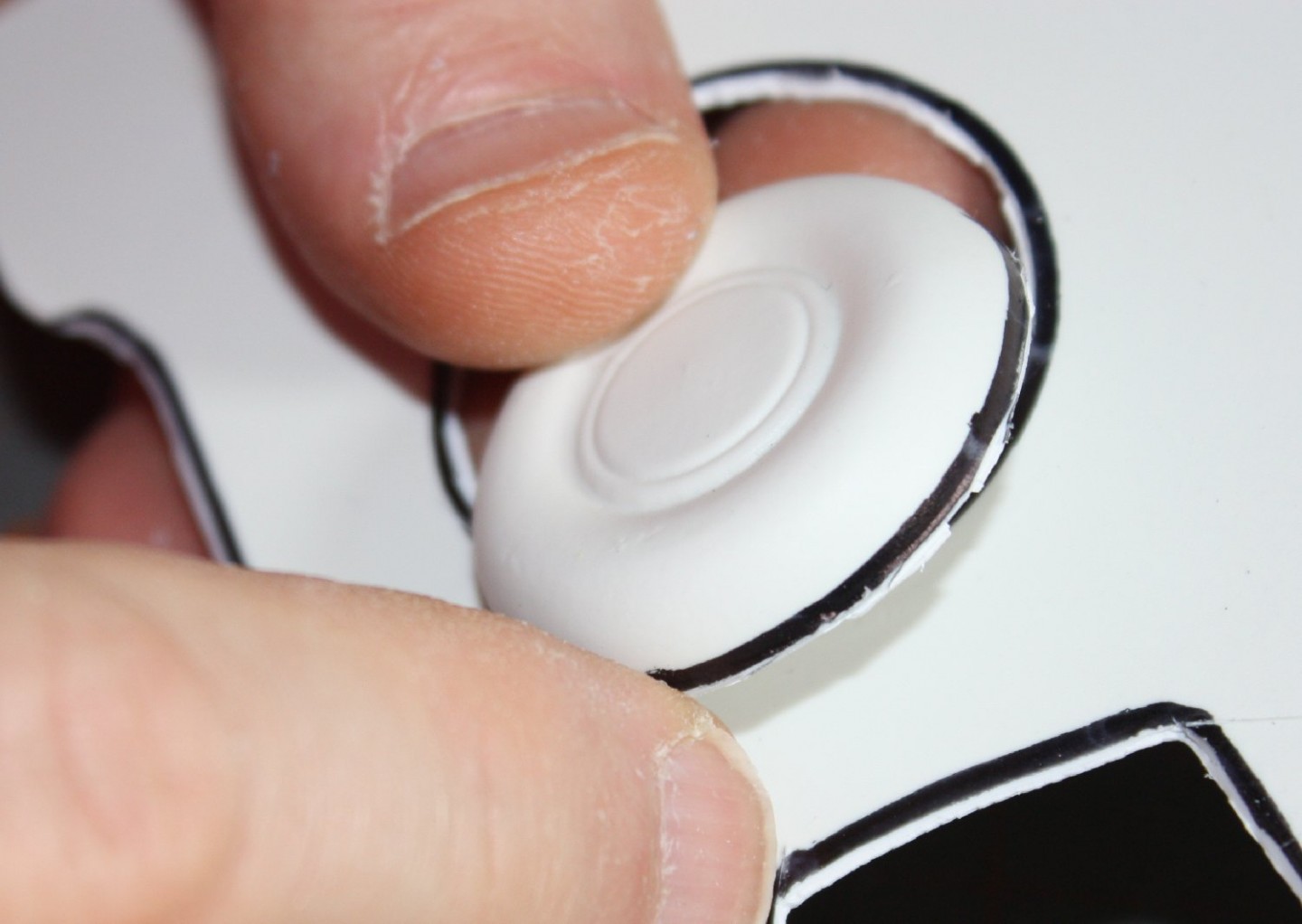
(It is sometimes true of ‘male molded’ components that the backing sheet thickness is required for a proper fit, unless the masters were properly made with an allowance for the sheet thickness.)  This is where having the clear parts to validate the fit of the matching parts becomes important.

Typically, however, the tiny bit of remaining backing sheet material must be removed for proper fit.  Parts_removal 6
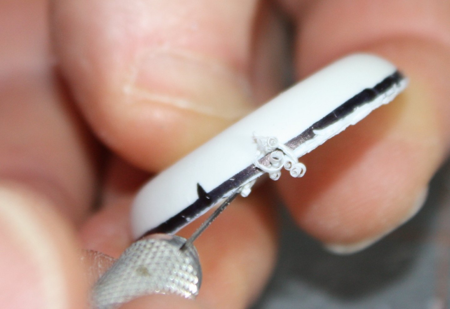
The plastic to be removed is visible because the ink line marks the edge of the cut, giving a trim line.  I start with a #10 Xacto blade (is is more rigid and has a better blade angle for this purpose), or sometimes a single sided razor blade, to shave the excess. Parts_removal 6A 
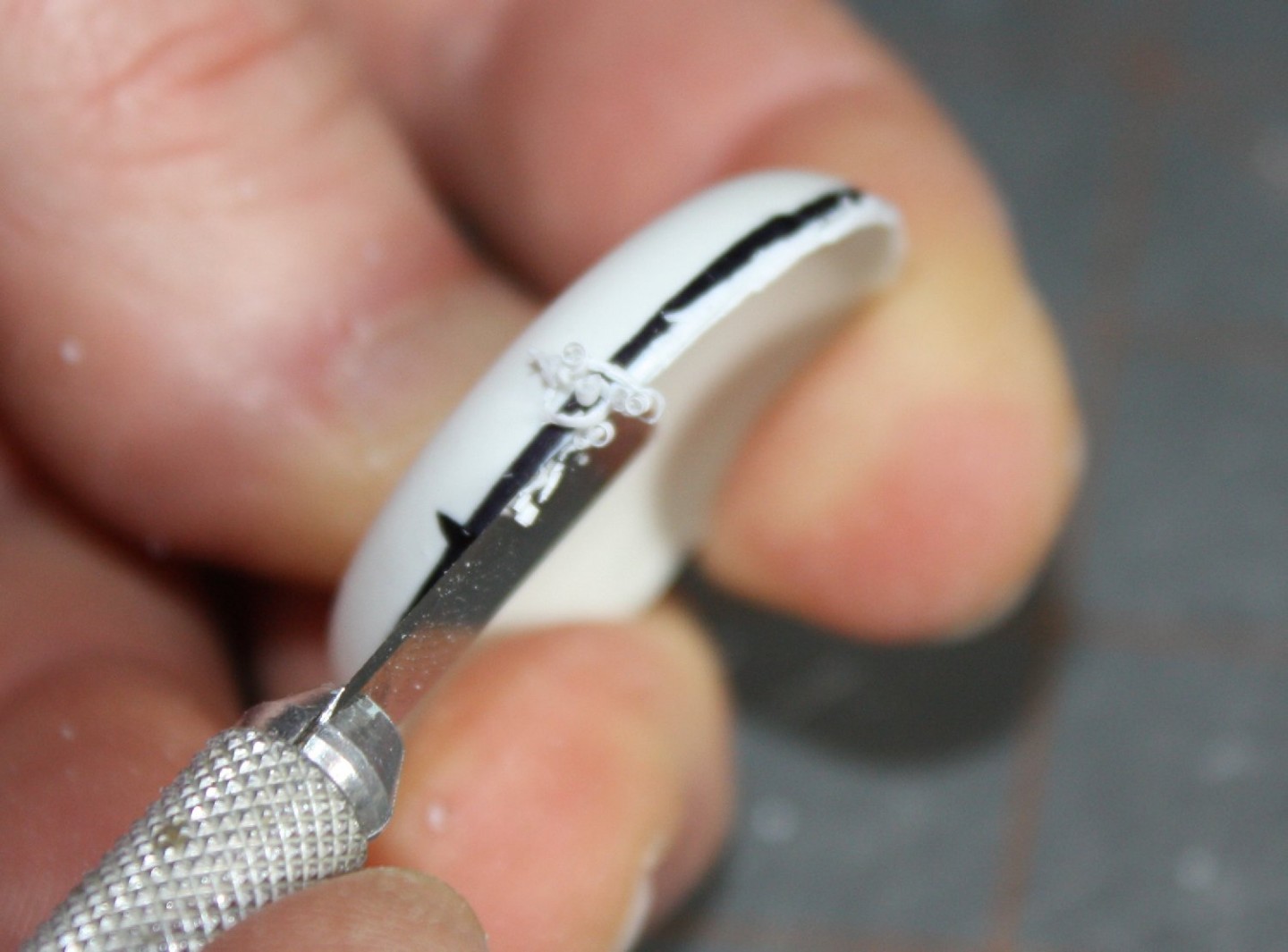
Using the blade like a tiny plane, I carve off most of the ‘wedge’, taking care to not allow the blade to wander past the ink mark and into the part itself (or my fingers!)  My goal is quickly remove most of the excess and roughly set a perpendicular edge to the part.  Parts_removal 6B
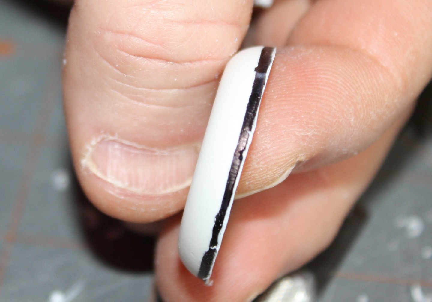
Just take care when trimming to keep your fingers clear & the blade ‘constrained’ (i.e., place your fingers so the blade is braced & cannot move or ‘jump’ very far) to avoid cutting yourself.  Granted, this takes a bit of practice!

Once the ‘shaving’ is done, I finish up with a sanding stick or block.  My sanding tool has to have a flat, rigid backing to achieve the desired flat edge – so no foam sanding sticks or pads (they can deform.)  The sanding direction depends on the part and how much needs to be removed.Parts_removal 7  
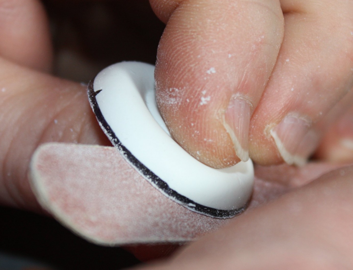
Sanding across the edge will remove material faster but with less precision than sanding along the edge’s axis.  Since the part is thin and can flex easily from side to side, cross-cut sanding is used initially with a finish sanding using long strokes along the edge to smooth any unevenness.  (Sighting along the edge helps to keep things straight.)  As always, avoid going past the ink mark.  Be aware that the dry ink may actually ‘flake off’ as sanding progresses, so take care to stop once the marked edge is just about reached.Parts_removal 8

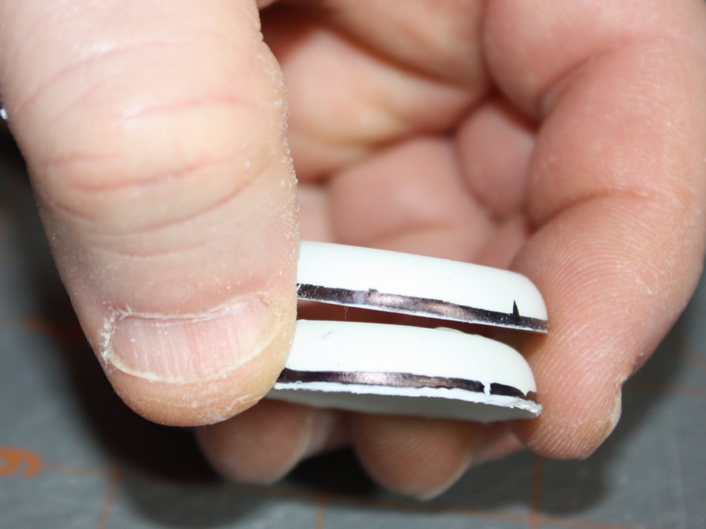
I will dry-fit the parts during sanding so I can take advantage of any opportunities to improve the fit of the parts.  If there is any undesired asymmetry, ‘over sanding’ the offending part will help the problem but this is usually accomplished once the basic cleanup is done.

With very little practice, removing vac parts is quick and satisfying.

<Go to Part 3
Go to Part 5 >
Posted in Modeling | Tagged , , , , | 2 Comments

P4M-1 Martin Mercator: Kit Review & Build – Part 1
avatar

1:48 Scale Martin P4M Mercator by RCM (Robert’s/Combat Models)

Martin_P4M_Mercator_small

Order via website: www.combatmodels.us
(kit 48-020 w/ resin detail set)  $59.95 plus shipping

Part 1: First off, let me share with you that this will not be a quick process.  I had decided, in spite of past experience with Combat Models vacuform kits, that I would attempt their P4M-1 because I really wanted a Mercator model.  In 1:48 scale, the Mercator is impressively large, as it should be.  The real deal was no lightweight, being a four-engined patrol-cum-ELINT aircraft.  (The engines were two Pratt & Whitney 4360 ‘corncob’ radials that each shared a nacelle with a Allison J-33 turbojet – the same engine that powered the P-80 fighter.)  The ‘Merc’ spanned 114 feet and was 85 feet long, or  28.5 by 21.25 inches in scale.  A big model no matter how you slice it.

So, with a kit on order (along with the optional resin ‘detail set’, offered as a bundle by Robert’s Models) I picked up a copy of Steve Ginter’s Naval Fighters Number Thirty-Seven: Martin P4M-1/-1Q Mercator monograph as a supplement to the material I had previously gleaned from the Web and from a visit to the National Museum of Naval Aviation‘s archives  to photograph relevant pages from the NATOPS and Tech manuals they hold there.  Having all this reference material helped with my decision to tackle what I suspected would be a pretty rough kit.  Little did I know!  But I get ahead of myself…

To be fair, the Combat kits being offered by Robert’s Models are from another era of ‘vac’ modeling.  These kits do not represent the current state of the art for a modern, good quality ‘multimedia’ vacuformed kit.  Robert‘s addition of resin ‘detail’ parts is an attempt to update the kits to a better standard.

Vacuform kits have always been something for the ‘hard core’ enthusiast, at least amongst plastic model kit builders.  Typically, these kits are the product of a ‘lone gunman’ working in his garage or similar facility, making masters by hand with all the precision, or lack thereof, that their personal craftsmanship could muster.  Some were more successful than others since making vac kits is, to be honest, not rocket science – but it can be akin to an art (some say a ‘black art’!) [See the series on vacuform modeling HERE]

Some makers, like Bill Koster of Koster Aero Enterprises, had actual model industry experience (Bill worked at Monogram) and could produce kits that were the equal or better of any injection molded kit with regard to engineering, accuracy and value.  But at the beginning of the vacuform ‘movement’, there was a wide range of ‘adventures’ to be had.  More typical was that the end result was more dependent on the builder’s skills than the  maker’s efforts.  This is why even to this day, the mention of a vacuform kit causes most modelers to break out in a sweat (assuming they even know what one looks like.)

kt_box

Large box protects kit in the post

It is upon this field of dreams I pondered the Mercator, assisted by my friend B. Brickhouse’s stories of his NARF (Naval Air Rework Facility) days working on such aircraft.   I had the motivation and the tools, and when the kit arrived, I had the raw material.

kt_box_open

Box contents include two large vac sheets, wrapped clear vac parts, plans and wrapped resin detail set.

Unfortunately, “raw” is an accurate description for this kit.  To give credit, the parts were cleanly molded, for the most part, and didn’t have any ‘subsided’ pieces which seemed to be common of Combat back in the day.  There were scribed panel details and such obvious features as windows present.

vac_parts

The two large sheets of vacuform parts. Notice the jet engine pieces.

On initial inspection, the vac parts looked promising but as I delved into the contents, I found a number of issues with the contours of the fuselage halves, the nacelles and the canopy.  I used the fuselage frames diagram in the Ginter book to check the length of the various features provided on the parts.  It became obvious that the fuselage was 1) too short, 2) the halves were seriously asymmetrical and 3) the distinctive ‘slab sided’ contours were not properly nor consistently depicted.  Also, the canopy, though clearly molded, was far too large & lacked the distinctive ‘bubble’ shape which means a new one will have to be made.vac_parts_closeup

resin_radios

Various generic resin radio ‘boxes’

resin_exterior

Provided resin pieces for exterior details

resin_interior

Essentially generic interior parts

The separate optional resin ‘details package’, available to assist with sourcing such parts as landing gear, props & engines plus various cockpit details, offered a selection of items that unfortunately bore only a passing resemblance to the originals.  resin_engineThe engines are just ‘fronts’ with cylinders that look like a twin-row radial vice the four row R-4360 ‘beastie’.  The wheels are properly sized but the hub detail is wrong being closer to the prototype than production items.  The main gear legs are too long, but do appear to have wire reinforcement.  In short, the parts allow for a generic impression of the needed details, but aren’t very accurate.  The pictures tell the tale. resin_wheels cockpit_resin

Needless to say, my assessment of the raw kit gave me pause.  I retreated to considering various ways to tackle the problems and challenges presented by the kit.  I knew I would not be satisfied to build it ‘out of the box’ since the resulting inaccuracies would be way too obvious to my now ‘research tainted’ eye.  So, it went back onto the shelf for a bit to await my enthusiasm to get recharged.
As an overview of the specific issues I know I will have to address, the following list is provided:

  • Insert three 6 scale inch plugs into fuselage to correct the length.
  • Re-contour aft fuselage to flatten the area adjacent to the rear gunner’s station.
  • Map out fuselage stations and related bulkheads so bulkheads can be added to assist with re-contouring the fuselage.
  • Build and detail the internal bomb bay to help support the fuselage and wing structure.
  • Engineer wing spars (forward & aft) to support the wing & set the dihedral.
  • Correct inner wing panel contours (incorrect airfoil shapes.)
  • Correct outer wing panels to depict the changes in airfoil as present on the prototype.
  • Build a cockpit, nose (nav & bombardier), radio and radar operator stations forward of bomb bay.
  • Build the tail gunner’s station interior.
  • Build the aft fuselage compartment (since the electronic recon operators stations are visible through the clear port waist window.)
  • Open bomb bay doors as almost always open when on the ground.
  • Remove & correct the ventral radomes and use as ‘masters’ for replacement parts and to allow duplication for the P4M-1Q version’s extra ‘domes.
  • Using spare Monogram B-17 wing parts, reconstruct the engine nacelles to correct shape.
  • Replace engine cowlings using a combination of spare P-61 & vac kit parts
  • Source replacement engines from either Engines & Things or from Model Shack parts.
  • Fill and re-scribe panel detail as too deep and irregular to be acceptable.
  • Correct resin main and nose wheel hubs to match production versions.
  • Scratch nose gear leg from brass tubing (provided part lacks the ‘slanted’ fork of the original.)
  • Trim and detail resin main gear legs.
  • Remove and correct shape of the forward main gear wheel fairings.
  • Use spare 20mm cannon parts from P-61 kit for nose and tail turrets.
  • Scratch-build new master for canopy once all fuselage re-contouring work complete.
  • Open forward and aft crew access hatches.
  • Scratch-build tail ‘bumper’ skid.
  • Add some interior lighting to help show off interior work; battery compartment can be incorporated in engine nacelles for ease of use & to help balance model on gear.

And that’s all for now… isn’t that enough?

Go To Part 2 >

Posted in Reviews | Tagged , , | 2 Comments

Saturday @ the Hobby Shop February 15th
avatar

Once again, we are slated to meet on Saturday, February 15th to spend time working on our latest projects and sharing the good word about ‘therapeutic modeling’ with any passersby.

If you can’t make one of the other out of state events, plan on coming out to the HobbyTown USA, Virginia Beach store (starting at 10 am then til closing) to join in or simply ‘hang out’ with your fellow modeling enthusiasts.  Bring as little or as much as you like, the idea is to have fun and possibly bring some unsuspecting member of the “public” over to the ‘plastic side’ of the Force.  As Roland Audet is fond of saying, ‘”Any day spent modeling is better than cutting the lawn!”IMG_9562

Posted in Club Events | Tagged | Leave a comment

2014 Old Dominion Open is a GO!
avatar

Post-show Report HERE http://hamptonroadsscalemodelers.com/wp-content/uploads/2014/01/2014-ODO-Info-lg1.jpg

The highly popular Old Dominion Open is revving up for its 2014 incarnation.   It is to be held on 22 February at the Richmond Raceway Complex in the Henrico Building (the same as last year.)  Chazz Klanian and the Richmond Gang have been keeping things moving along in their usual smooth fashion (a least they make it seem that way!)  Full details on the competition, vendors and other offerings can be found on the Richmond IPMS website HERE.Look for the Hampton Roads crowd to convene for an after-show dinner before hiking home.  Hope to see everyone there!

Google Map info HERE

http://hamptonroadsscalemodelers.com/wp-content/uploads/2014/01/2014-ODO-Info-lg1.jpg

Posted in Events | Tagged , | Leave a comment

Vacuform Aircraft Modeling – Part 3
avatar

Basic Techniques

Don’s Model Works, home of the late Don Bennett’s vacuform kit outlet (now taken over by his son Chuck) has an excellent writeup of the method similar to the one I use in removing and cleaning up vac kit parts.  I’ve tried several methods over the years and this is the quickest and most foolproof technique I’ve found:

http://www.donsmodelworks.com/ref/Hints_Vacuform_Models.pdf

Also, Brett Green over at Hyperscale compiled a similar vacuform ‘primer’ series you should check out:

http://www.clubhyper.com/reference/vacformbg_1.htm

The primary difference is that I generally have no need to use the old ‘sandpaper on a board’ step – a hand-held block wrapped with sandpaper is usually sufficient.  The key is to minimize the amount of excess plastic that must be removed once the pieces are cut from the ‘sheet’ of parts.  In Don’s writeup, he recommends finishing the file work with a bit of sanding on a sandpaper sheet to smooth the edges.  The trick to this method is when attempting to sand a part flat on sandpaper, it is very difficult to apply even pressure across the entire part – unless the part is ‘smallish’ to begin with – in which case it is then difficult to hold!  Being thin and flexible, vac parts are subject to ‘flexing’ when sanded on a board, giving uneven sanding pressure which then results in a poor fit.  This is the problem with the old ‘standard’ method of scoring around the parts, leaving a ‘border’ or ‘lip’ of plastic around the part then sanding on a sheet of sandpaper until the excess is razor thin and ready to ‘flake off’.   Invariably, the excess would have different thicknesses as a result of the inevitable uneven sanding pressure.   It is just nigh impossible to hold a part evenly, especially when working with larger parts.  Why work so hard!?

One challenge to a vac kit is the fit of the parts (if properly engineered to start) is highly dependent on the modeler’s skill at prepping the parts.  The work is not difficult, as little effort is needed to sand the typically soft styrene used.  In fact, this actually makes it pretty easy to over-sand the pieces.  On less well made kits, constant test-fitting is required to check the fit – which is sometimes better if the edges are not fully ‘dressed’.  Lots of test fitting should be done regardless of a kit’s quality.

Another major point concerns any clear parts provided.  In cases where the clear parts have a critical fit to the fuselage (such as with a B-25, for example, where the entire nose is essentially a clear part), preparation of the clear parts will also dictate fuselage fit issues simply because the clear parts typically cannot be modified to fit better whereas the styrene parts can be shimmed or trimmed as needed.  This is why the clear parts are the first thing to consider before cutting out and sanding the fuselage parts.  A ‘bubble canopy’ (for example) that fits atop the fuselage has less impact on the fuselage dimensions than a canopy that is supposed to have the same profile/ cross section as the fuselage.  In effect, because the clear parts cannot be altered (unless the modeler replaces the parts from scratch), they serve as the primary sizing constraint for any interfacing parts.

Once the parts are fully ‘dressed’ and all critical edges are sorted for the best possible fit, vacuform construction proceeds essentially the same as an injection molded kit, albeit one that will typically may need more scratch-building of details.  Extra support structure such as internal ‘bulkheads’ or ‘spars’ are often needed to properly support thin walled parts or to reinforce joints.   For example, fuselage shells benefit from having short, contoured ‘tabs’ glued to the inside of joints in an alternating fashion so to overlap to the other half, almost like the teeth of a zipper.  This promotes positive parts alignment and increases gluing surface area while providing internal support across the seams.  These tabs, made from the excess sheet stock, should be bent to a matching contour instead of being left ‘flat’ so to provide a better ‘gluing surface’ and prevent distortion across the seam.

Most of the material for the spars, bulkheads and tabs comes from the cut-off (excess) plastic sheet.  This extra plastic is perfect for fabricating needed structure & details including basic internal ‘boxes’ for wheel wells and cockpit bays (if not already provided as molded parts) as it is the same ‘stuff’ as the molded parts.  Again, precision in contouring the mating surfaces will pay off with trouble free and strongly glued joints.

Keep in mind that proper contouring of the mating surfaces are important to get a good bond.  Consider when plastic sheet is cut, the edges will have an angle due to the “V” shape of the blade.  This cut edge usually needs to be smoothed & ‘squared off’ with a sanding stick or block for best fit.  Also, the raised ridge along the cut should be sanded down to prevent it interfering with anything else later – unless it provides some detail!

Precise, exact fit between components is a hallmark of the modern injection molded kit.  For a vac kit, the precision achieved is up to the builder.  This is part of the allure of vac kit construction – the satisfaction that comes from personal craftsmanship.  Plus, there is the side benefit to learning the fine art of “fettling” (adjusting parts fit by hand) which is useful with injection kits as well.  Once a modeler starts looking at parts less as ‘Lego blocks’ and more as unfinished components that *may* need further attention, a whole range of kits become ‘do-able’.  Fully developed, this mentality logically leads into the realms of conversion, modification and even scratch-building of entire models not commercially available.  In short, the modeler has no limits to what he/she can tackle using skills developed mastering the ‘fearsome vacuform’!

<Go to Part 2
Go to Part 4>
Posted in Modeling | Tagged , , , , | Leave a comment

‘Detail & Scale’ Adopts New Publishing Paradigm
avatar

At the recent IPMS/USA Region 2 Convention in Roanoke, I had a wonderful opportunity to speak with Bert Kinsey, the publisher of the famed ‘Detail and Scale’ series of (primarily) aircraft detail & history monographs.  Over the years, the series has gone from a smallish pamphlet format printed on heavy paper stock to a full size format of slick paper with high quality, mixed full color/ B&W images.  Now, with his ‘ebook’ on the F3H ‘Demon’, he is taking the next logical step and going full ‘digital’.  He demonstrated it to me on a Kindle (will be available in iBooks format also), explaining how the large resolution images could be “zoomed” for better viewing – as could the text, which is certainly a boon for guys with ‘older’ eyes like me – plus the obvious portability of an e-publication.
DnS_flyer_scan_small
Consider this: I have several full size filing cabinets (and a couple of bookcases) stuffed with paper-based references (soft-back books, magazines, etc.) that would, if digitized, fit into one small corner of a current ‘hard drive’.  If all of one’s personal library were fully indexed and available to bring up on a ‘screen’ of one’s choice at a moment’s notice, imagine the saving in time finding and accessing material for a modeling project.  Of course, such capability comes with a price in hardware, internet services (and a power bill) but if you’re reading this, you probably already have that covered.  All you may still need is an ebook reader, unless D&S is to provide a computer compatible format (lots of technical challenges to protect copyright with standalone file formats like PDF.)  As such, Bert’s first eBook is part of the ‘charge’ into the publishing future – really the “now” (which also means Dr. Who should also be appearing any time now…)  More information – and a bit of demonstration – on the release (apparently not quite out yet…) can be found at:

http://www.detailandscale.com/

Posted in Reviews | Tagged , , , | Leave a comment

Menu Sign-up for Club Holiday Potluck Dinner Meeting – 20 Dec 2013
avatar

Please put your planned food item and number of attendees into the “Leave a Reply”for this post; read the other Replies to see what everyone is bringing (I will consolidate the list as we progress for easier reading.)  Remember, bring serving utensils, hot pads, etc. for your food item (preferably with your name affixed with a small piece of tape!) as there will not be anything provided for serving.  If you plan on a soup or chili item, plan on bringing disposable bowls or small cups as appropriate. Extension cords will be provided for those having crock-pots, etc.  Also, if you know you won’t be attending, please leave an RSVP to help with the ‘head count’.

There are a couple of supporting “items” that need to be brought, so if you want to bring them instead of a food item, please do so (if more than one person wants to split these items, feel free to say so and coordinate with your partner):

1) Paper plates (good quality to handle lots of food), napkins, cups and plastic utensils for 60 people (at least)

2) Two large bags of ice & a large cooler to hold the ice, scoop for the ice and 8 x 2-liter bottles of soda (selection of regular and diet varieties)

We hope to have a balance of items of course so main ‘entree’ items, cold & hot side dishes, salads and deserts should be considered.  If any items are vegan/vegetarian or gluten-free, please make a note (index card for example) to go with your dish.  It would also be nice to provide a note if anything has nuts or diary in it – if not already obvious.

Thanks to everyone for taking time to coordinate for our potluck, it is always a wonderful evening.  I look forward to seeing you all!

UPDATE – List as of Dec 15th:

Baked Ziti (sausage & cheese)
Pasta Salad
Sandwiches
Turkey & Ham Sandwiches
Deviled Eggs & Ham Sandwiches
Hot Wings
Ice, cups and soda drinks

Posted in Club Events | Tagged | 11 Comments

Saturday @ The Hobby Shop – November 9th, 2013
avatar

Once again, the Day is just around the corner!  Get your “battle boxes” out and dig out a portable project, then plan on coming by the Club Saturday Build Day at HobbyTown- USA (VA Beach store), anytime from 10 am to 5 pm.  Recommend bringing a desk light to assist the overhead lighting that is provided and an extension cord if you have it.  You can bring a lunch or pop next door for some sushi (Misako buffet) or Subway if you wish and spend the day working on some plastic and sharing knowledge with your fellow of like ilk.

Refreshing the display case is planned; if you wish to retrieve a model from the case, please let me (Robert Beach) know ahead of time.  Also, if you have something fairly fresh for the case, make sure to bring it along.  Having examples of current store inventory is always welcome to help promote our host’s modeling sales so keep that in mind also.

Look forward to seeing you there!

Posted in Club Events | Tagged | Leave a comment
Gallery

HobbyTown USA (Virginia Beach) – Shop Report
avatar

This gallery contains 44 photos.

A long-time presence in the local area hobby scene, the Virginia Beach HobbyTown USA store is a fixture in the Southside modelling community. Based on experience, not all HT-USA franchises are equal so it is fortunate that “our” store is … Full Article→

Posted in Industry | Tagged | 1 Comment

August HRSM meeting minutes
avatar

Club Vice President Ken Patrick brought the meeting to order at 7pm. Seventeen members were in attendance.

Old business: 

September swap meet date is still undetermined since the usual Sept. 21 date is not available. The church has another function scheduled for that day. Ed Rose is working with the church to find another date — either the week before or after.

Raffle status: So far, we have sold $56 in tickets according to club treasurer Gary T.  Following that announcement, he sold more tickets and we are now only 15 away from breaking even and having the raffle. If you haven’t already purchased a raffle ticket, now would be a good time.

Chapter Contact Robert Beach reminded the club about the annual tank farm open house near Manassas, in case anyone wanted to attend.

New business:

Member Bill Wesley reminded folks to start planning for the 2014 convention in Hampton. He suggested starting early to save money for the vendor room. He also gave a good tip to use your smart phone to comparison shop while at the convention.

He also suggested that HRSM sponsor a theme award at the 2014 convention. We would do the judging and awarding of the trophy. Idea tabled for further discussion.

No additional new business, meeting adjourned and Bill Wesley conducted a demo on making jet intakes.


Posted in Club Meeting Minutes | Tagged , | Leave a comment