

This gallery contains 12 photos.
Pictures from the January Meeting From the November 2012 club show and tell:
This gallery contains 12 photos.
Pictures from the January Meeting From the November 2012 club show and tell:
Now we’re on a roll: actual bonding of the major sub-assemblies into proper hull halves, assembled sail, and establishment of the means of securing the two hull halves so that access to its interior is assured and easy. From this point, to improve the clarity of the discussion, I’m going to refer to the fittings kit parts by both the noun-name and letter identifier pictured in Part-4 of this Cabal Report.
Hull quarter assembly is a departure from what the kit supplied instructions advocate. Remember, the kit, as packaged, is intended to be assembled by average hobbyist into a seamless, non-functioning, static display model. However, as an R/C submarine, we need access to both the hull and sails interiors; we have to take measures that permits access those spaces. So, what I describe below is the creation of upper and lower hull assemblies that can be opened up to access the interior of the hull, and the devices mounted on the hull but contained within the sail.
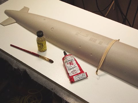
Gluing bottom hull halves together using flat surface
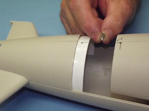
Access to the interior of the hull is through the horizontally split upper and lower halves. At the stern and bow the longitudinal break transitions to a radial break at the lower bow and upper stern. The radial flange forward draws the hull halves together forward, and a single machine screw, running through the after radial flange, compresses the hull halves at the stern.

Using assembled (and cured) bottom to ‘key’ upper half assembly
The forward and after lower hull quarters are welded together using solvent type cement. As you can see, the two hull quarters are mounted on a flat board to insure that their edges fall along the same plane. Note that a rubber band is used to push the after end of the forward quarter down hard onto the radial flange of the after quarter. Just as in metal welding, which involves pre-heating of the weld area, the contact areas of the plastic to be bonded is treated to make it receptive to deep fusion once the state change is effected to the parts being joined. Before assembly, the radial flange of the lower after quarter and mating surface of the forward lower quarter are soaked in the very thin solvent cement to soften those surfaces. Then, quickly, the gelled solvent cement is beaded onto the flange and the two hull quarters assembled on the flat board, the rubber band made up, and the work left for twelve-hours to harden.
Once the center, radial union between the two lower hull quarters has hardened, the assembled lower hull is taken off the board, inverted, and the two upper hull quarters are set upon it – a test dry-fit. Any sprue left at the equatorial separation line between the lower hull and two upper hull quarts is identified and cut and filed back till a tight fit between the three hull pieces is achieved.
Take things apart, insert two slivers of wax-paper onto the edge of the lower hull over the radial joint – this to prevent any adhesive that runs down from the upper hull pieces from getting onto the lower hull piece. Don’t worry, if you keep the wax-paper slivers small enough they will conform to the tongue-in-groove union enough so as to not distort the fit between the three hull pieces too much. Or, you can wax the edges. Your call.
Lay the after upper hull quarter down, get it to register with the lower hull and hold the assembly together with rubber bands. Soften the flange of that piece and corresponding inside surface of the forward upper hull quarter with brushed on thin solvent cement, then smear on beads of gelled cement to the surface of the flange and quickly position the forward upper hull quarter atop the lower hull and make the assembly fast with rubber bands. Leave the upper hull to dry twelve-hours.
The reason I’m so specific as to how you assemble the hull quarters is this: As the R/C SKIPJACK features a hull that opens up at its centerline equatorially, it’s vital that the upper and lower hull index together as well as possible owing to the fact that the only clamping force applied when they are assembled is at the extreme bow and extreme stern. Any misalignment between the two hull halves during assembly of the quarters, and you would suffer unsightly open seams between the halves.
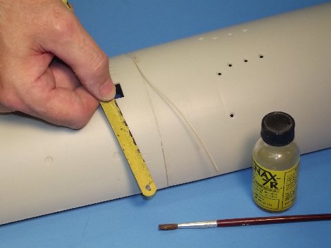
Applying stretched ‘sprue’ filler rod to hull seam (cleaned out with hacksaw blade)

Making the Z-union cuts to the hull halves (stern from upper, bow cut from lower)
As in metal welding, filler rod is sometimes employed when welding large plastic parts together, this to achieve like material build-up and to bridge significant gaps between the two items being fused. Here, a length of sprue (liberated from the SKIPJACK kit), has been heat-stretched to a mean diameter of .025″. This polystyrene rod used to fill the inevitable seam between the two hull quarters of the upper and lower hull pieces. To carry the metal welding analogy a bit further as I explain what we’re doing here: As pre-heating of metal parts to be joined is done to enhance fusion, wetting the groove between the hull quarters liberally with thin solvent cement works to soften the plastic which encourages the polystyrene molecules to interlink with those of the adjoining filler rod and hull quarter. (Unlike adhesive bonding, we’re welding the parts and filler rod into a whole. Once the operation is complete, no bonding agents are left, only a fused together assembly of identical material – in this case, polystyrene plastic. The strongest possible union of separate parts). If need be – to insure an open seam of uniform width and depth to better receive the filler rod – use an eighteen-tooth-per-inch hack-saw blade to achieve a uniform .025″ wide by .025″ deep groove for the filler rod. Lay in the filler rod, brushing on solvent as you go. Things get gummy as you work and soon the rod dissolves into the adjoining material. The result is a near perfect fusion weld between the forward and after hull quarters. This is going to be an R/C model submarine … we’re not screwing around here! Strength and avoidance of dissimilar substrates are vital considerations during assembly.
Carefully following the inked on radial lines, a razor saw was used to remove the tail-cone from the after upper hull quarter, and bow from the forward lower hull quarter. Using a wide hard-block, sand the radial faces of all parts with #240 sandpaper. If you were careful you lost no more than 1/16″ of kerf, that will be made up later with CA-baking soda filler.
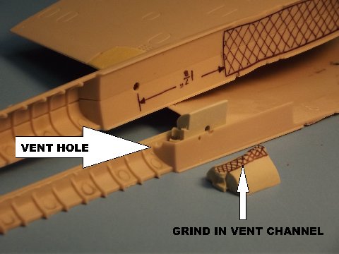
Placement of the diesel exhaust fairing vents
When the R/C SKIPJACK leaves the surface, an unobstructed path for venting air, trapped in the diesel exhaust fairing, has to be provided. Failure to get all the air out of the fairing will upset the boats trim and make it difficult to hold exact depth when cruising along at slow speed. So, the following operation has to be done before securing the sail foundation pieces (sail-to-hull mounting foundations-R) to one half of the sail assembly: Grind a 1/8″ deep by 1/8″ wide vent channel atop the after foundation piece. A corresponding vent hole is drilled into the top, forward bulkhead where the exhaust fairing meets the trailing edge of the sail proper.
You will need the ability to flex the bottom of the sail a bit to get the lower sail plane bell-crank (sail plane bell-crank-T) on and off its bell-crank shaft retainers (sail plane bell-crank shaft retainers-S). To accomplish that the sail foundations are glued to only one side of the assembled sail. This permits the unglued underside of the sail to pull away from the other sail half when flexed to install or remove the lower sail plane bell-crank.
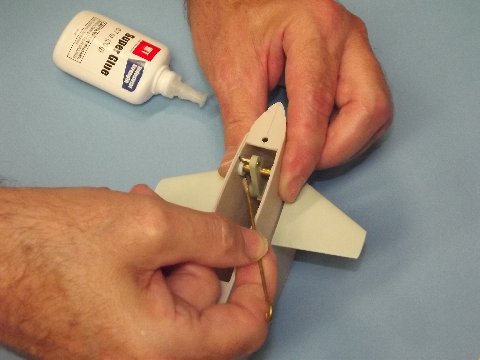
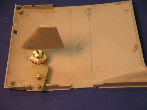
You see here how the sail plane operating shafts fit within the rather thick hub of the resin upper bell-crank (sail planes and bell-crank-Q). The gear portion of the upper bell-crank engages the gear portion of the lower bell-crank which works around its shaft to rotate the upper bell-crank when subject to the axial motion of the pushrod that runs from the motor-bulkhead of the SD.
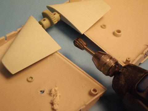
Modifying the sail plane pivot holes to accommodate control shaft/crank
Here I’m grinding away the raised, molded bores of the original operating shaft holes projecting from inside the sail halves. The hole, as it is, is too big for the 1/8″ diameter sail plane operating shaft. You see between the trailing edge of the sail planes and the ground away bore of one sail half the as of yet untouched bore. A small resin bushing (sail plane operating shaft bushings-N), installed into the original hole reduces its diameter to the required 1/8″ bore required by the sail plane operating shaft. The two bushings are pushed in and CA’ed in place. Note that a set screw, set within the hub of the upper bell-crank unit, secures the operating shaft of a sail plane – these set screws easily reached from the opening in the bottom of the sail assembly.
Critical placement & securing of the lower crank retainers inside sail
Tape the halve of the sail together. install the sail planes by running each operating shaft into the bore of the upper bell-crank. With the two sail planes lined up parallel to the top of the sail, and the center of the gear section facing down and perpendicular to the planes, tighten the two set-screws to secure the planes to the upper bell-crank part.
The two resin lower bell-crank shaft retainers are placed on the ends of the brass pivot pin, and the entire unit installed into the inverted sail and oriented so that its teeth meshed with those of the upper bell-crank. Squeezing the hull halve together between thumb and forefinger, to hold the shaft from moving, tack-glued the retainers to the sail halves – use only enough CA to hold them in place. Check that rotation of the lower bell-crank caused free unbinding rotation of the upper bell-crank. Break and reposition the retainers as required until free, minimal back-lash operation of the linkage is achieved.

Example of glue technique on a taped assembly (note removed planes)
Position the clear piece that represents the emergency stern-light within the sail, then assemble the sail and hold it together with masking tape. Avoiding those areas where masking tape is (you don’t want the thin glue to get sucked into the tapes edges by capillary action), brush thin solvent cement along the seam at the leading edge of the sail, along the top of the sail where the sail top piece will sit, along the trailing edge of the sail, and over the seam atop the diesel exhaust fairing. Also run cement onto these seams from the inside. Leave the assembly to dry for a few hours. DO NOT apply cohesive glue to the bottom seam of the sail assembly. Remember, you want to flex the bottom portion to get the lower bell-crank shaft in and out of its resin retainers.
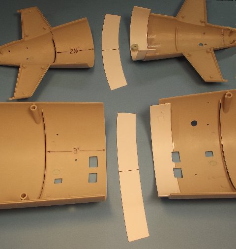
Illustration of Z-union flange assembly
Clamping glued flanges; note vent hole overlap of lower flange
To the right are installed flanges. Center and left are yet to be installed flanges and the hull sections they go into. you want one-half of the tail-cone flange (after radial flange-V) to project past the radial edge. However, you want only 3/8″ of the forward flange (forward radial flange-W) to project past the bow pieces radial edge. As they arrive, the stiff, polystyrene flanges are flat. You can easily put a curl into them by running a flange piece over a small dowel as you apply pressure between dowel and finger as you pull the flange through. Keep at it until the flange retains a curl close to the radius of the part it will fit within. Test fit the flanges to the tail-cone and bow piece. Onto the bow piece flange mark with pen or pencil where some of the flange overlaps two of the flood-drain openings. Once you’ve affirmed a good fit of the flanges, remove them, cut away those areas of the forward flange so marked, coat the flange and hull pieces with thin solvent cement to soften they’re surfaces, apply gelled cement, then quickly assemble the flanges to their respective hull pieces, clamp and let sit for at least twelve-hours.
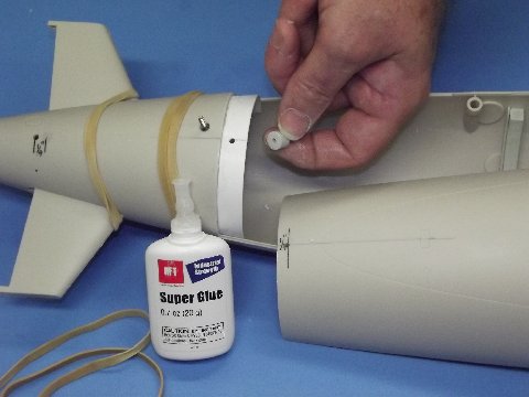
Z-union securing screw and flange foundation piece
Beauty of the Z-union – one screw holds it all together!
Time to work out the means by which the upper hull will be made fast to the lower hull. Rubber-band the removed tail-cone to the lower hull. Place the upper hull onto the lower hull, insuring that the indexing pins and long horizontal edges of the two hull halves fully engage – leave the sawed off lower bow piece off-model during this operation. Rubber-band the two hull halves to they don’t lift up on you. On the upper hull, 1/4″ forward of the after radial edge, on centerline, mark off and drill a 7/64″ hole that will pass the 4-40 securing screw – drill through both the upper hull and after radial flange.
Remove the upper hull. Soap the threads of the screw (to keep adhesive from sticking), insert the screw thread through the flange hole; hold the foundation under the flange hole (upper hull securing screw and foundation-X) and run the screw into the tapped hole of the foundation and tighten till the foundation is pressed tight against the bottom of the flange; apply some CA between the foundation and flange – not too much!. Spritz on some zip-kicker to cure the glue; unscrew the fastener; with a counter-sink bit bevel the hole in the upper hull so that the screws head sits flush.
A single 4-40 flat-head machine screw passes through a hole in the upper hull half, pushing it all down upon the after radial flange. Up forward, the radial flange of the lower hull captures the bow piece attached to the upper hull, pulling the two hull halves together there. The Sharpe-kachur Z union at work!
Trackbacks:Attached is a .pdf file with our website statistics. Pretty darn impressive for a little modelers group! BTW, these stats ignore Robert Beach and Myself since we are always in here editing and such.
Analytics HRSM Audience Overview 20120401-20130103
Your Webmaster,
Ken Patrick
OK, you’ve culled out the unneeded Moebius 1/72 SKIPJACK kit parts; inventoried the fittings kit parts; degreased the resin parts; and scoured and sanded the hull, sail, and other appendages. Time to mark off and open up the hull and sail holes. These holes are needed to pass linkages, vent the hull and sail, permit flooding of the hull and sail, pass the control surface operating shafts, and to pass and accept the threads of screw fasteners used to hold the hull and sail assemblies together.
As the kit comes in the box, the hull is broken down into four large hull sections or quarters – two upper hull quarters and two lower hull quarters.
With the exception of the resin blanking plugs, don’t permanently glue anything together yet, though some of the below shots show assembled hull quarters. Do as I say, not as I do. Trust me, there’s a method to the madness here. Also, you’ll note in some photos that I have two SKIPJACKs in the shot. I’m not showing off. I do it this way to convey as much visual information as possible.
Fine. Let’s get to work:
You want to check the fit, within the hulls stern, of the stern planes and rudders, as well as the running gear foundation.
An error we failed to catch on the test shots was the too far forward positions of the rudder operating shafts. I corrected that by moving the center of rotation a bit farther aft to the cord of supplied resin rudders. However, you will have to relocate the rudder operating shaft hole, top and bottom.
Take the two stern (aft) hull quarters, identify the 3/16″ diameter resin blanking pieces, and insert and CA each disc into a rudder operating shaft hole, leave a bit of the blanking disc standing proud of the hull so you can sand it to contour to the tight radius at that point of the stern. On the inside of the two stern quarters, grind flush the raised flanges of the former rudder operating shaft bores.

Rudder stem correction blanks and new hole locations.
Back on the outside of the hull halves – from the center of a blanking disc, measure 1/4″ aft and drill a new 1/8″ diameter rudder operating shaft hole, top and bottom. You’re now ready to test fit the resin rudders and stern planes, running gear, and their associated yokes, push-rods, and intermediate drive shaft.
The function of the two white-metal yokes, which interconnect opposed control surfaces, is to provide clearance of the centrally running intermediate propeller drive shaft.
We’re going to test-fit the stern control surfaces and running gear into the lower after quarter of the hull and get comfortable with how the two types of control surface operating shafts make up to the yokes; make up the push-rods to the yokes and make up the intermediate drive shaft to the propeller shaft coupler. All this to check the components for fit and proper operation and to give you a good look at the assembly in operation (a chance to appreciate my magnificence) – something you won’t be able to do once the a stern cone portion of the aft upper hull quarter is permanently glued atop the aft lower hull quarter.
The rudders are rather straight-forward in that the upper portions of those operating shafts are permanently encapsulated in the cast resin rudders with projecting end of each operating shaft running directly into a rudder yoke bore and made fast with a set-screw. The rudder operating shafts have machined flats, insuring non-slip alignment between the two rudders when made up to the yoke.
The stern plane operating shafts, through necessity, have to be removable from the stern plane pieces themselves. This is because the outboard ends of the control surfaces fit within horizontal extensions that project aft and block a straight-in insertion of the stern plane with its operating shaft installed. So, I’ve made the stern plane operating shaft removable. Making up a stern plane to its yoke goes like this: astern plane is held behind its horizontal stabilizer by masking tape; the stern plane yoke, with attached push-rod, is suspended within the stern with the aid of either a long hemostat or needle-nosed pliers. The stern plane operating shaft (it’s flat oriented to present to the tip of the stern plane set-screw) is pushed through the hole in the center of the horizontal stabilizers outboard bearing, through the bore of the stern plan, and into the bore of the yoke till the outboard end of the operating shaft is flush with the outboard face of the horizontal stabilizer bearing. The operating shaft fully inserted, the stern plane set-screw is tightened (don’t over-tighten or you’ll strip the resin thread), keeping the shaft from rotating within the stern plane. Finally, the inboard end of the operating shaft is secured to the yoke by tightening the yokes set-screw. You want to orient the stern planes chord line perpendicular to the yokes bell-crank arm. Whew!
Oh … and for the sake of scale, orient the stern planes with the operating shaft set-screws on the bottom, out of eye-shot.

Stern control and propeller linkages. Note control rod ‘Z-bend’ tips
Employing 1/16″ diameter brass rod, make two push-rods, 7″ in length,each with a Z-bend at one end. One push-rod makes up to the rudder bell-crank, the other push-rod makes up to the stern plane bell-crank. Later, the forward end of these push-rods will receive a magnetic coupler that will engage a counterpart that makes up to a SD push-rod and servo. Magnets are used to couple the two linkage elements – no back-lash, no tools, no sweat. More on that later.
Two oblong holes, one in each of the bottom hull quarters, are intended to accept the stud of a display stand. Fine for static display of the model, but of no utility to those wishing to R/C the SKIPJACK model. Use the two resin blanking plugs to block those holes, as you did with the rudder holes -then grind away the raised flange within the hull quarter over those blanking plugs.

Blanking plug an molded ‘features’ that require removal by grinding
Take the two resin propeller shaft foundations and, after grinding away the radial and longitudinal raised braces at the stern of the two plastic aft hull quarters, test the foundations for a tight fit. Keep the aft lower hull quarter propeller shaft foundations in place for the next step, the dry-fit of the running gear and control surfaces.

Test fitting the stern components (shows push-rod connectors also)
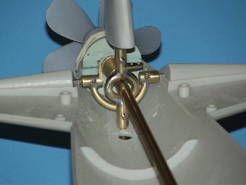
Install the two rudders and two stern planes as seen below. And check for non-interference of control surfaces and yokes through the full travel (not to exceed 35-degrees left/right and rise/dive). Note how the intermediate drive-shaft runs through the center of the rudder yoke and over the swing-arm of the stern plane yoke.
The intermediate drive shaft is a 8 1/4″ long length of either .014″ wall thick, 7/32″ outside diameter brass or aluminum tubing with half a Dumas nylon dog-bone inserted into each end – each dog-bone pined to the shaft with a transverse length of 1/16″ brass rod, “peened” at each end. You’ll work out how much dog bone half projects past the tube as you integrate the running gear with the SD.
You’re going to saw away portions of the stern and bow from the respective hull quarters to establish a Z-type separation line between upper and lower hull sections. This is a long accepted hull access methodology popularized by R/C submarine pioneers, Dan Kachur and Greg Sharpe. This type break between the two hull halves provides for quick access (only one screw at the stern holds the hull halves together), is strong, and is less susceptible to flexing than a simpler horizontal break that runs completely around the bow and maybe even the stern
With the Z-break, a single screw presses the after halves of the hull together as a radial capture flange forward works to press the forward halves of the hull together. To achieve this Z-separation, you’ll remove portions of the bow and stern and weld them to the opposing hull section. Confusing? Look at the pretty pictures!
Take the forward lower hull quarter and aft upper hull quarter in hand and put the other quarter hull section out of the way so you don’t grab one of them by mistake when you start marking and cutting.

Marking the Z-flange cut lines on the hull pieces
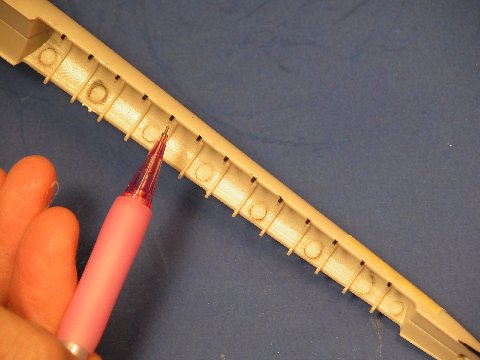
Now, to mark the radial lines around the hull quarters where you will saw them free. Any number of ways to accurately mark off a radial line on a tapered body-of-revolution. But, the easiest method, presented here, is to take advantage of the internal stiffening ribs molded within the hull quarters, using them as both guide, and datum line from which to identify the distance from bow and stern to cut the bow piece and stern piece away. Study the photo.
Load your compass with a Sharpie fine tip permanent ink pen. Let’s start with the forward lower hull quarter: Identify the second radial stiffening frame from the bow, that’s our datum line. Set the compass distance between point and pen tip at 3”, place the point into the right-angle union between hull and frame. Be careful to maintain the line between point and pen tip parallel with the hull quarters longitudinal axis as you move the compass laterally, mark a radial line into the inside of the hull quarter, that inked-in line denoting the bow cut line.
Do the same for the aft upper hull quarter. That datum frame is the one at the leading edge of the horizontal stabilizers. Set the compass so that the radial line established is 2-1/4″ forward of the datum frame.
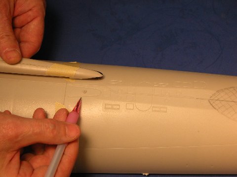
It’s much easier to follow the cut line if it’s on the surface of the hull quarter, so now you have to transfer the inner cut line to an outer cut line. Plug in a 100 Watt light bulb, and use it to back-light the interior of the hull quarter so you can see the internal radial ink line through the translucent plastic. Pencil in cheat marks to the surface of the hull over the line you see through the hull. After enough points are put down to get an accurate indication as to the lines true form, lay down some masking tape, it’s edge at the cheat-marks, and ink in a proper cut line to the outside of the hull using the edge of the tape to guide the Sharpie pen point.
Remember, cut off the stern of the aft upper hull quarter, and cut off the bow of the forward lower hull quarter. Don’t screw up! And don’t cut these pieces off until later, we’re just marking things off at this point. Check twice and cut once!

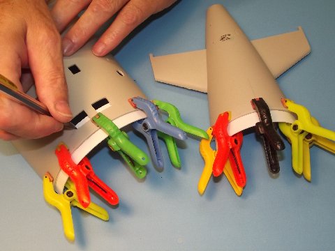
Upper hull screw holes, vents and sail bellcrank openings (see measurements in article)
Mark, then drill or grind out the opening atop the two hull quarters. Right, you see two SKIPJACK upper hull pieces, the one atop has its holes opened up. The lower unit has just been marked off as to hole shape, location, and size. Use new (sharp) drill bits spun at low speed. Styrene takes to the bit well, but keep the pressure light as you punch through. The indented round depressions on the sides (upper and lower) of the hull quarters indicate drill sizes to use. For holes larger than 3/32”, start the hole with a 1/16″ bit, this serving as a pilot hole that better directs the cut of the larger bit that follows. When using high-speed cutting bits, do not let the bit stay in the work too long or the plastic will melt.
Punch out 7/16″ diameter holes in the centers of the six ballast tank vents on the forward deck flat. Do the same for the four ballast tank vents on the after deck flat. Don’t touch the four big MSW holes on the aft lower hull quarter after quarter hull section, those will later be covered by PE gratings.
The following hole locations are now marked off along center line on the forward upper hull quarter. Measurements are taken from the projecting nib, marked ‘datum’ on the above photograph, just aft of the forward deck flat:
Once you have marked out the holes that go under the sail, snip the two nubs (indexing pins, if you will) off the hull and at their former location, drill 7/64″ holes. These will pass the 4-40 machine screws that hold the sail assembly down onto the upper hull. There is a third nub, back near the after portion of exhaust fairing, on the aft upper hull quarter. Snip it off too, but drill no hole there yet.
Flip the forward upper hull piece and work on the inside now.

Upper hull hole opening for sail plane operating bellcrank (inside view – note orientation labels)
Open a long, narrow extension of the square hole you just made. This will eventually pass the push-rod magnet that makes up to the magnet at the base of the lower element of the sail plane bellcrank assembly. Note the orientation, and the side where you put in the new cut, and it’s measurements. Now, grind away. The outboard longitudinal side of that the hole butts up against the raised portions of hull under the sail – those raised portions accommodate the longitudinal indexing troughs atop the hull. The photograph shows how the linkage goes in there once all these preliminary operations are out of the way. Take heart … you’ll eventually get there, pal.

Opening and screw hole locations in the sail assembly
With masking tape, put the two sail halves together, time to open up the bottom of the sail to pass the bow plane linkage (mounted within the sail) and snorkel head-valve assembly (mounted atop the hull, but fitting within the installed sail). The upper sail has already been opened up, the lower sail has been marked off and is ready for hostilities. I forgot to indicate on the model the distance from the forward hole (both of them already provided as the kit arrives) to the forward transverse line of the hole. It’s 3/16″ from the hole’s center.
Tack-glue the forward and after resin foundation pieces within one half of the sail, then tape the other half of the sail onto it. With a Sharpie pen mark off the spot where you will drill a 3/32″ hole and tap it for a 4-40 machine screw. Take everything apart and punch those holes and cut the threads into the sail foundation pieces.

Marking holes on resin foundation parts in sail using pre-drilled holes
Most apparent in this photo, at the base of the sail, at its perimeter, the plastic extends down into long-running lips that engage the deep troughs set within the top of the hull. The two 4-40 machine screws running up from within the hull into the resin foundations fixed in the sail make fast the sail to the hull, yet provide for quick and easy separation of the two for transportation, adjustment or repair.

Before and after for the lower hull openings, plus the needed tools
The many square holes you have to punch open in the bottom of the two lower hull quarters is done with drill, square files and sanding sticks. The work goes pretty well if you take it easy and outline the inset gratings molded into the plastic with a Sharpie pen. Yes, you’ll loose all that beautiful detail, but to be a practical R/C model submarine that works as a wet-hull type, you need to lose the flood-drain grate detailing. Get to it!
I suggest you punch out all the holes before sticking the hull quarters together, the parts are easier to handle when they are smaller assemblies. Note on the lower hull that I’ve also taken advantage of the engraved lines of the torpedo tube shutter doors to open those up – that model will later be outfitted with six practical launchers.
A torpedo firing SKIPJACK is an option for you way-over-the-top R/C submariners. The torpedo nest foundation is provided with your fittings kit. If you go the hostility route, here’s the weapon system you would need to make the local lake safe for Democracy. (http://www.sub-driver.com/torpedo-systems/torpedo-system-1-72nd-scale.html) and a technical paper on the system. (http://support.caswellplating.com/index.php?/Knowledgebase/Article/View/359/47/torpedo-launcher-instructions-172)
Before installing the two sets of SD foundations, shock absorber, and SD Velcro strap foundation, it’s wise to mark out a center line to the inside of the lower hull quarters.
Examine the two sets of resin SD foundations provided. The smaller set goes aft and the cut-outs within those clearly defines where they butt up against a frame in the aft lower hull quarter. The other, larger set of foundations fits against the forward face of the aft-most frame in the forward lower hull quarter. Note that the circular edge at the top of these foundations is not concentric with the circular edge at the base. On both sets of foundations the narrower portions of the pieces of the foundation halves meet at the bottom of the hull – get that straight before CA’ing them permanently in place!

Marking the SD shock absorber position against the foundation frame
With the forward set of SD foundations glued against the frame, butt the after end of the shock-absorber (where the pin projects up) up against the forward face of the SD foundations. Center it, then using a thin pencil lead, mark onto the hull where the holes will be drilled to pass the six securing 2-56 machine screws.
Remove the shock absorber and grind away a 1/2″ wide, 3/8″ deep channel down between the two halves of the SD forward foundations. This channel permits disassembly of the shock-absorber components, should that every be necessary.
The forward end of the strap foundation butts up against the after face of the forward most frame of the aft lower hull quarter (the tall end of this resin piece goes forward, the shorter end goes aft). Lay the piece on its side within the hull and mark off where you will punch two 3/32″ diameter holes into the bottom of the hull, these will pass two 2-56 flat-head machine screws that secure the strap foundation piece to the lower hull. To be clear, the notch in the foundation piece goes down (against the hull) since the strap passes under the foundation.
Before drilling a hole, I push a pointed rat-tail file hard into the plastic, a sort of ‘pilot-hole’ that works to guide the drill bit as I open up the hole. Keeps the work centered.

Drilling holes for the SD shock absorber (note the foundation frame is not in place in picture)
Here I’m punching out 3/32″ holes to pass the flat-head 2-56 machine screws that secure the SD shock absorber to the bottom of the forward lower hull quarter.
On the outside of the hull, I will bevel these holes with a counter-sink bit to accept the flat-head screws that secure both the shock-absorber and strap foundation.
Trackbacks:
This gallery contains 20 photos.
John Nugent reports: Here are some of the pictures from the Golden Corral Military Appreciation Night exhibit, November 12, 2012. The year, Golden Corral actually kept the exhibit up for the remainder of the week, which gave more people time … Full Article→
Only the most dense of you would miss the sub-text of the last four chapters. I’ve been selling you on both the Moebius Models plastic model kit of the SKIPJACK, as well as the Caswell-Merriman 1/72 SKIPJACK fittings kit. That said – and now distancing the discussion far enough away from the good Moebius people so as to spare them any collateral damage from the following admonition – I’m going to give you, those of you who wish to acquire both products, a dose of reality.
Anyone who can smear glue on styrene, and finds the Moebius SKIPJACK an attractive subject, I encourage to buy it and have a ball. It’s an easy kit to assemble, and is a stunning display piece. Get two, three, hell … get a case of those kits! You have my blessings. Knock yourself out.
However, you few out there thinking of going the full mile; those who plan to also get the Caswell-Merriman fittings kit, ask yourself this: Why? That fittings kit is for the conversion of the Moebius and Scale Shipyard 1/72 SKIPJACK kit to radio control, that fittings kit is good for nothing else. You sure you want to do this? Think about this long and hard before you plunk down your cash.
You’re not listening, are you? Fine. I’ll try this:
The most demanding arena to play in within the R/C vehicle hobby is R/C model submarining. The construction, set-up, successful operation, maintenance, and repair of R/C model submarines takes considerable skill and determination – this is not an entry level activity; you don’t do this successfully unless you already have experience assembling, setting up, and operating other, simpler R/C type vehicles. You don’t run a marathon out of the womb. You don’t get into R/C model submarining (at this level) unless you are an accomplished R/C flyer, driver, or robot fighter. Crawl, walk, jog, run! Same with R/C submarining. Don’t buy the fittings kit (any fittings kit) unless you know your way around R/C systems, are pretty good on the sticks, have substantial model-building skills, and you have money to spend.
If your primary income is a government check, stop right here, pal, this is not a poor man’s game. It’s for elite Craftsmen. Do you qualify?
Or, would you rather I sweet-talk you, suggest that your poop don’t stink, then sell you stuff that is way out of your league?
The rest of the chapters to this Cabal Report constitute the ‘how-to’ of integrating the fittings kit elements to those of the 1/72 SKIPJACK kit. All my warnings issued, I have to make the assumption you have a well outfitted workspace, you have good hands, you can problem solve without having to be spoon-fed, and you have the cash to play this game.
About the money: The SKIPJACK kit and fittings kit are a small fraction of the eventual outlay of funds to see the project through. You still have a Sub-driver to buy. Add to that the batteries, charger, R/C system, angle-keeper, fail-safe, speed controller, servos, Lipo-Guard, BEC, receiver, and so forth. Before you even get your completed R/C model submarine to the waters edge you will have pumped over fifteen-hundred-dollars into the project. Do you want to risk all that cash as you send your little submarine to the bottom of the lake? Think before you whip out that credit card!

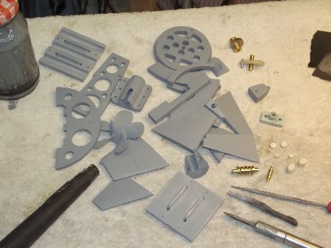
Plastic kit parts used with the fittings kit (bottom right)
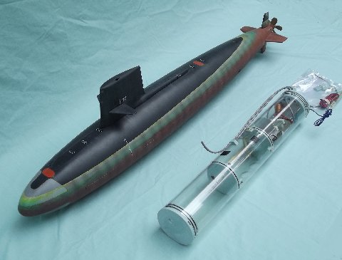
The Moebius kit parts you will use, if you convert to R/C, are seen here – all the other items that come in that box you can bag and put in the ‘parts bin’. To the right of the decal sheet are the contents of the Caswell-Merriman fittings kit. Integrate these items with the SKIPJACK and it will be ready to receive the 3.5 SKIPJACK Sub-driver (SD), and Caswell 1/72 SKIPJACK ballast weight-foam kit.
What is it they say about a boat being a hole in the water into which you shovel money? They’re right. Have I scared you away yet?
OK, let’s say you got stupid, made your purchases, and are now hiding your credit-card receipts from the Wife. Let’s get to work:
During the casting process, the resin forming tools are given an obscenely large amount of silicon mold-release spray in order to extend tool life and ease the extraction after the resin changes state. Much of this primer and paint inhibiting oil stays on the part, and has to be completely removed before you can get any type of adhesive bond to it. Degrease ALL of the resin parts.
Take the torpedo tube foundation assembly apart (if you’re going to us it, it’s the only optional item in the fittings kit), pull the operating shafts out of the stern planes, as well as their set-screws; and gut the SD shock absorber – this to get full access to the resin surfaces without hardware getting in the way. Put some gloves on, or this stuff will tear you up. And work in a well ventilated space, don’t get any in your eyes, and this stuff is very flammable so make sure you don’t have any ignition sources nearby. Nasty stuff, but it will degrease your resin parts. Do not get any on the styrene parts!

Resin parts and lacquer thinner used as a degreasing agent
The degreasing liquid of choice is lacquer thinner or straight acetone: a resin part is immersed in the liquid for a minute or so (too long and the part starts to wrinkle), and as it soaks, scrub all surfaces of the part with a very stiff brush, like the stencil-brush pictured above. Pull the part out and scrub the surfaces you can get at with a soaked abrasive pad. Dunk the part one last time to wash off residue, pull out and wipe and blow to remove any clinging lacquer thinner/acetone.

Scouring powder, pad and rinsing water
Pull up a small tub of fresh water, some scourging powder, a fresh abrasive pad (that’s never seen lacquer thinner or acetone), a virgin stiff brush, wash-cloth and paper towels. And don’t let the pretty picture above fool you, it’s going to get messy. In fact, this task is best done in the tub with the shower running. In a cup put in some scouring powder, add some water and mix it up to a gooey slurry. Dip your abrasive pad, wash-cloth, and stencil-brush into the abrasive and rub it vigorously over and into all polystyrene parts as well as the resin control surface parts. Keep the work wet. Which abrasive polishing tool you use depends on the geometry and accessibility of the item being scrubbed.
When done, put the work under warm running water and scrub till the soapy scouring powder is washed completely away.
This step removes any parting grease still clinging to the injection formed parts (yes, plastic model kits sometimes come out of the box NOT READY for priming and painting). This coarse polishing imparts small scratches onto the parts surface, ‘tooth’ that will greatly enhance the sticking power of later primer, cohesive, filler and paint. This is a step that should be performed on all injection formed plastic model kits, no matter what you’re going to eventually do with them. But, wait! There’s more …

Removing flash from metal prop casting
I’ll assume you know how to make and use a sanding-block. You’re going to use both hard (stiff piece of wood) and soft (flexible piece of foam or rubber) backing blocks. Hard blocks on parts of simple curve, like the above control surfaces and sail sides. You’ll employ the soft blocks on structures of compound curve, like the hull quarters, top of sail, fillet between exhaust fairing and sail, and propeller fillets. I classify those great foam-core sanding sticks as mini soft sanding blocks – you see one of those used above to knock flash off the cast white-metal propeller.
You’ll employ #240, #400, and #600 grit wet-and-dry sandpaper. but this initial sanding of all styrene and resin control surfaces parts will be done with #400 – to insure the removal of all substances that would inhibit adhesion and to render mechanical tooth to the parts to better hold the filler, putty, and primer applied later. You want the primer and paint to stick to the work, don’t you? You don’t want to suffer ‘fish-eye’ in the paint job, right? There is a strong possibility you will suffer these problems should you fail to degrease, coarse polish, and sand the parts. This is what can happen: You assemble the parts, fill the seams, prime, paint, applied masking and you paint again, you yank off the masking tape and peel all or some of the primer-paint under the masking off the models surface …. Yikes! The primer was blocked from proper adhesion to the plastics/fillers/putties surface because contaminates got in the way.
An R/C model experiences a lot more stress on its coating system than a static display model safely tucked into a display case does. The R/C model is subject to collisions and grounding, and handling ‘accidents’; its coating system is exposed to a significant amount of UV which only non-hobby type coating systems are formulated to tolerate; and the different expansion rates of the coating system and substrates puts a great deal of shearing force between the two (a very warm model submarine that has been sitting under the hot July sun, suddenly dunked into sixty-degree fresh water). All examples of environmental conditions that attack your nice paint-job. You want that primer, filler, putty and paint to stick to the model parts as tightly as you can arrange. Hence all the substrate preparation I’ve outlined above. Not suggestions. These are things you got to do.

Materials to make custom sanding pads
The flats at the outboard ends of the stern planes, the top of the upper rudder around the anchor-light, the safety-track running atop the upper hull and the near right-angle union between the horizontal stabilizers and hull require careful, precise sanding with a stiff, but thin sanding tool.
Such an abrasive tool is made by folding over a piece of suitable grit sandpaper to form a crease at its center, you then spray some CA setting solution onto the back-side of the sandpaper, coat one half quickly with some CA, then fold it over and clamp it till the CA cures hard. The stiff, double-sided sanding pad is then trimmed at all edges and corners with a scissors, and it’s ready for use. Just another abrasive tool in your arsenal of sanding sticks and sanding blocks. A very handy tool indeed.

Kit hull quarters showing unequal ‘bowing’ resulting from molding stresses
Some, but not all of the Moebius kits suffer from an outward bowing (warp) of the two hull bow quarters. You see this in the photo here. You can live with it and rely on the registration pins and the tongue-in-groove edges that run the length of each hull quarters longitudinal edge to pull the parts together, or you can apply some heat to the two warped hull quarters and coax them back to the correct diameter. That’s what I did. An operation not for the faint of heart!
 A hair-dryer is not going to cut it – you need an industrial strength hot-air gun like this one I got from Harbor-Freight (I LOVE Harbor-freight!). To avoid disaster, you must keep the gun in motion over the work, and to get as even a heat distribution to a hull quarter as you can.
Be warned: you fail to evenly heat the work and produce a hot-spot you will either punch a hole in the part or distort it beyond repair causing you to issue a primordial scream and stomp around in a blind rage. Some fun, huh!

Careful work with the heat gun to correct hull curvature
Believe it or not, it worked for me – but then again, I’ve been doing this sort of scary sh*t for decades. There’s a lot of burned, cut, sawed, melted, and stomped-to-death failures in my wake.
I simply held the work in one hand, applied the heat evenly, and when things got toasty (painful) I squeezed the hull into a proper half-round. Don’t wear oven-mitts when you do this – you’re pinkies will tell you when things get hot enough.
A smarter way of doing this is to attach two wooden fences to a flat board, and jam the hull quarter between the fences, apply the heat, then let the work sit there till it assumes room temperature – the smart-money is on that technique, not the hand-held one.

Two types of solvent ‘cements’ used to weld the plastic parts
Unlike resin and metal parts, polystyrene – the plastic most injection formed kits are made of – is a thermoplastic that lends itself to chemical and thermal welding: the introduction of heat or a solvent breaks the molecular chains, a characteristic of a solid, and momentarily changes the state of the material to a liquid or semi-liquid where, upon freezing or dissipation of the solvent, the new array of interlinking molecules cross over the seam line bridging the former gap, leaving a single item where there was once two. A fusion weld. The process is called cohesion.
And that’s what the two solvent type cements above do. They melt styrene plastic. This is the preferred means of attaching styrene pieces to one another. The very thin solvent, applied with a brush, is used to soften the surface of the parts to be welded – akin to preheating metal before effecting the weld. The gelled solvent cement, in the red tube, gives up its solvent much slower, giving you the time to apply it to one softened surface and mash it down onto the other, and work out any misalignment.
When you stick two or more pieces together by introducing a third ingredient that remains to anchor the pieces together, that’s called an adhesive. CA, epoxy-glue, white glue, horse-glue, solder (yes, solder) and so many others are adhesives. No fusion here, it’s the adhesives wetting ability, to get in close to the atoms of the substrate, that puts into play a mysterious (to me anyway) ‘bonding force’ between the parts and adhesive. Though, in some arrangements, mechanical tooth or physical interlocking of the parts can and will enhance the holding power of the adhesive bonded joint. We’ll use CA on this job to join dissimilar materials to one another – situations where a fusion weld is not practical with street-legal chemistry.

David’s preferred primer materials
If at all possible use the DuPont brand primer (Nason), paint (Chroma-Color), and clear-coat (Chroma-Clear) with flattening agent. You’ll find this stuff at a local automotive refinishing supply house. Look ’em up!
Second choice is rattle-can paint from a box-store, something like RustOleum or Krylon brands. But, decant the stuff and shoot it through a medium sized single-action air-brush/gun like my old trusty Paasche H-model seen above – use the big tip and needle. Get cans of the primary colors, black, white, and primer – the primaries so you can mix them up to get the colors you need (very dark gray, brick red, and international orange). And pick up low-tack masking tape and a color wheel.
Don’t use hobby-store paint. It’s all crap, that stuff is formulated to be safe, not good. You need a paint that has high abrasion, UV, and chemical resistance; and is flexible and has superior sticking power.
(You’ll find nothing useful in today’s brick-and-mortar hobby store but glue, blades, and magazines. The pimple-faced counter-person, likely some punk R/C racing type with metal studs and rings projecting from lips, lids, and ears; an uncooperative, smart-ass, cash-register monkey more preoccupied with the timing of his next smoke-break than any technical or stock questions you need answers for. You dare talk to one of these dorks and all they can hear is a Charlie Brown – Whaa, whaa-whaa, whaa, whaa-whaa, whaa… @#$% em!)
Do your tool and consumables shopping at the DIY box-store, auto refinishing house, Harbor-Freight, and the Internet.

Showing the application of the ‘spot putty’
You’ll use an air-dry putty for scratches and low-fill seam work. I recommend the Nitro-Stan line. you can use it straight out of the tube (also available in cans), but you’ll find that it’s best applied with a brush, screeding blade (that yellow thing next to the tube of putty), or finger. When brushing it into tight unions cut the putty a bit with lacquer thinner, makes it flow better. The automotive refinishing supply house has it or something very much like it, likely 3M Red.
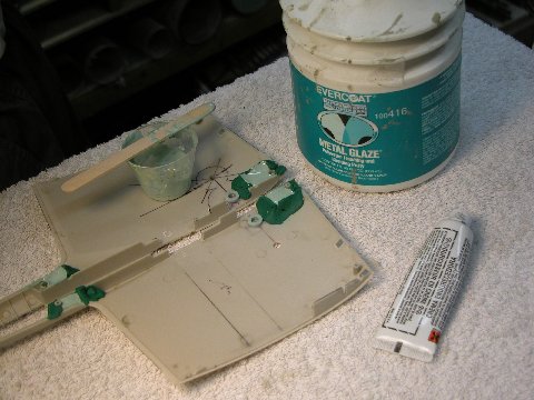
And get some two-part, polyester auto filler, like Bondo, for the deep seams and re-contouring work. I prefer the Evercoat brand. You can get that from the Caswell company. In fact, you can get just about all the tools, abrasives, and other consumables from that single source. (http://www.caswellplating.com/)
Yes, yes …. I’m a whore. Sue me!
Trackbacks:Parts One through Four serve as preamble to the meat of this series, a detailed discussion – an instruction manual, if you will – on how to employ the Caswell-Merriman ‘Moebius 1:72 SKIPJACK Fittings Kit’ to convert the static display plastic model kit to a practical, well running and robust R/C model submarine.
I had little input as to how the kit was engineered. The only input I had was to ask that there be a longitudinally running, horizontal break between the hull pieces, be they two long ones, or the top and bottom halves divided into quarters. This to achieve a removable upper hull half to afford internal access for R/C versions of the model. I also asked that the hull pieces be of substantial thickness (3/32″ the ideal); that the lower and upper hull halves (or quarters) be outfitted with internal stiffening frames; and that there be provided a tight fitting system of pins and tongue-in-groove hull edges that would insure positive registration of the two removable hull halves. Other than that, the guys at the point of manufacture did all the engineering – and what a wonderful job they did, resulting in a sturdy, well fitting, easy-to-assemble plastic model kit with a minimum of parts.
The mock-up SKIPJACK kit – though fabricated in a 3D machine – was broken down into parts and the parts indexed as the eventual kit would be. Inspection of the mock-up kit revealed that my wants had been incorporated. I was delighted as in this game you have to be ever mindful that the product is primarily targeted at the vast majority who will only assemble the kit for static display. Fortunately the things I asked for did not impact on the cost of the kit, so they were incorporated.
So, with my work for Moebius completed, I directed my considerable talents and good looks to the service of the Caswell empire – the design, fabrication, and packaging of R/C conversion kits needed by our customers who wish to turn the Moebius SKIPJACK into a well-running R/C model submarine. Before the kits hit the West Coast, I had completed all the fittings kit masters and tools, and was well underway with part production. I could do that as I made use of the second generation test-shot kit parts to give form to the masters that were conformal to the inside surfaces of kit parts. Masters were built up from test-shot kit parts (all the control surfaces) automotive filler, brass, plastic sheet, RenShape, foam-core PVC sheet, and white-metal castings.
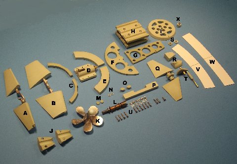
Parts Legend
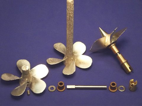
Below is a visual presentation of the items that make up the Moebius 1:72 SKIPJACK fittings kit, along with a table below denoting the name and function of each item:
A stern planes and yoke
B rudders and yoke
C after Sub-driver foundations
D Sub-driver shock absorber
E forward Sub-driver foundations
F nest transverse bulkhead
G nest keel piece
H torpedo tube nest foundations
I torpedo muzzle bulkhead
J propeller shaft foundation
K propeller
L propeller shaft, bearings and coupler
M hull rudder hole blanking discs
N sail plane operating shaft bushings
O hull stand hole blanking pieces
P Sub-driver restraining strap foundation
Q sail planes and bell-crank
R sail-to-hull mounting foundations
S sail plane bell-crank shaft retainers
T sail plane bell-crank
U mechanical fasteners
V after radial flange
W forward radial flange
X upper hull securing screw and foundations
The first area I addressed as I went about the chore of creating masters was the stern. Specifically, the two-piece foundation needed to mount the propeller shaft bearings. I started by removing the strengthening rib and single longitudinal brace in the area of the two stern hull quarters. I CA’ed a half-circle sheet-plastic transverse dam forward and a blanking sheet butted against the after end of the hull, where the base of the propeller hub would fit. These dams are to contain the thinned down filler used to give form to the foundation masters.
I waxed the inside of the containment to prevent the hardened filler from sticking to the styrene.
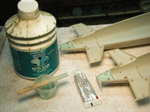
Pouring the filler into the stern
I thinned the filler with lacquer thinner till the mix was runny enough to insure a bubble-free fill of the stern areas with the gooey stuff. I mixed in a little hardener, poured and pushed the stuff into the stern areas and waited for the filler to cure.
Automotive filler will shrink a bit if used straight out of the can. Even more when you cut it with thinner. So, I was compelled – after the two halves of the propeller shaft foundation master cured – to pull them out, re-wax the interior of the hulls, smear uncut catalyzed filler on the contact face of the masters, and smashed them into place, where they remained till the filler had hardened. The glaze I put on the parts made up for the shrinkage and produced a tight glove fit to their respective spots on the hull stern pieces.
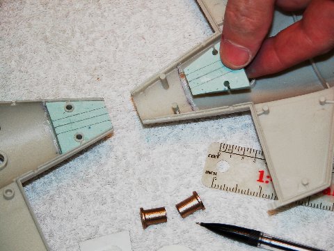
Preparing to fit the propeller shaft foundation parts for the Oilite bearings
The two halves of the filler formed propeller shaft foundations were marked out. Filed out those channels would form the bore hole through which the two propeller shaft Oilite bearings would fit. Extreme care was taken to insure that the center-line of the two channels ran perfectly in alignment with the hulls longitudinal axis.
To make the reach of the long push-rod between the after end of the Sub-Driver (SD) – the watertight cylinder containing the propulsion, ballast, and control sub-systems – motor-bulkhead a simple one, I employed a partial bevel-gear linkage within the sail to translate the axial motion of the push-rod (mounted up against the inside of the upper hull) to the rotary motion, up within the sail, needed to activate the sail plane operating shaft.
Sail plane activation bevel gear mounting
The masters of the two partial gear elements are seen here. A small cylindrical magnet within the eventual cast resin lower gear element engages a magnet at the forward end of the sail plane push-rod. A similar magnetic coupling at the after end of the push-rod produces a near slop-free linkage between servo and sail planes.
These masters, along with the others, would be degreased, cleaned up, (pickled, if metal), primed then used to make rubber production tools.
I needed solid foundations within the forward and after bottom ends of the sail through which securing machine screws would hold the sail down upon the hull – permitting removal of the sail from the hull for sail plane linkage and snorkel induction head valve and float adjustment or maintenance.
Pouring sail mounting blocks
The masters of those foundations formed – like the propeller shaft foundation masters – from thinned down two-part automotive filler poured into the area of the model part where the eventual model part would fit. Here I’ve formed the containment dams from oil-based modeling clay. However, with these, the last step was to assemble the two sail halves and hold them tight with masking tape as the last application of filler, applied to the outboard faces of the foundation masters, acted as an adhesive to form two solid foundation masters.
Scale Shipyard SKIPJACK and Sub-Driver ‘proof of concept’
As I worked up the masters for the Moebius Models 1:72 SKIPJACK fittings kit, I developed the jigs, templates and plumbing masters needed for production of a dedicated 3.5″ diameter, SAS type, single-motor SD to handle the ballast, control, and propulsion of this kit. I used my old, faithful Scale Shipyard 1:72 SKIPJACK model as the evaluation hull as I modified and eventually froze the design of the new SD.
Test fitting of control yoke masters with dummy drive shaft
I fabricated the stern plane operating shaft yokes and the rudder operating shaft yokes from brass rod. Here I’m checking the yoke masters as well as an assembled propeller assembly with mock intermediate drive shaft to check for non-interference of the control surfaces through their full 35-degree travel up/down, left/right. Once all was found to operate properly, the yokes were removed, fillets built up with CA and baking soda, pickled, primed, used to make a disc type metal casting centrifugal tool.
Part masters finished and primed prior to making rubber ‘tooling’ molds.
Most of the masters are now in primer gray and ready to produce the production fittings kit tooling.
The first set of fittings kit production tools were made from the relatively hard BJB Inc.,TC-5050 silicon, platinum cured, room temperature curing (RTV) rubber. The relatively ‘hard’ rubber is best suited to hold the masters when the time comes to make duplicate tools or copy masters. More on that, perhaps, at a later date.
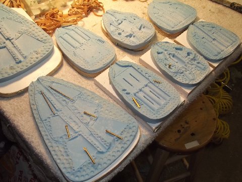
Rubber ‘tooling’ for fittings kit parts
This shows the four two-piece production tools used for resin part production. Note that the control surface cavities have been outfitted with brass operating shaft inserts, as well as brass rod mandrels in the torpedo launcher foundation tool, and a brass pivot pin in the ‘accessories’ tool. The inserts will be partially encapsulated in the hard resin and become operating shafts, pivot pins, and cylindrical bores.
With all inserts in place I spray in some ‘Mann-200’ mold release spray, dust on some talcum powder (a ‘bubble getter’), assemble the halves of a tool, sandwich each tool between wooden strong backs, and clamp the assembly tight with rubber bands. Catalyzed resin is poured in through a single sprue hole where it is distributed to the cavities through a system of runners – displaced air is routed out of the cavities through a separate vent-channel system. I’m a master at rubber tool design.
The ‘Mann-200’ keeps the polyurethane resin from sticking to or attacking the rubber, but not completely as these tools have a 100-200 cycle life before becoming too brittle for use. Talc acts as a wick to pull resin into portions of the tools cavity that otherwise would trap and hold air pockets, which evidence on the part as pinholes.
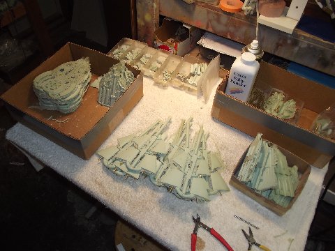
Raw resin castings (with talc powder at back of table.)
Most of the Caswell-Merriman 1:72 SKIPJACK fittings kit is fabricated from cast polyurethane plastic – some of those raw shots seen in the center of the table. I remove the individual parts from the trees, machine back the stubs, and file off most of the flash. No attempt is made to degrease the resin parts. I leave that for the customer.
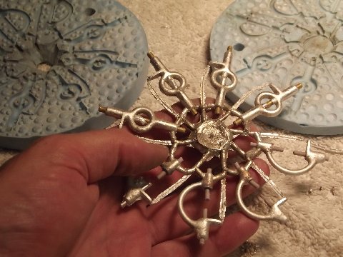
Disc mold for ‘spin casting’ of metal parts
This disc-shaped rubber tool is spun in a modified blood separation centrifuge as molten white metal (an alloy of tin and antimony) is poured in through a sprue hole at the center of rotation. Rubber mandrels set within the cavities form the bores for the stern plane and rudder operating shafts. Another virtue to the TC-5050 is its ability to handle low-melt metals that can be poured successfully at a temperature below 600-degrees.
Once the yokes are snipped away from their runners, the mandrels are pulled and each yoke is drilled and taped to receive the operating shaft retaining set-screws.
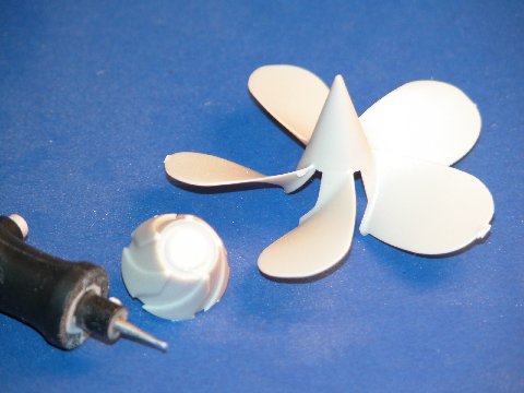
The white-metal SKIPJACK propeller – both the Moebius kit and the Caswell-Merriman R/C conversion fittings kit represent the original five-blade ‘power’ screw – starts life as a gravity poured white-metal casting, which explains the long sprue on the center propeller. Tall to take advantage of the pressure head produced when pouring the molten metal into the screw cavity of the mold: the taller the sprue, the more hydrostatic pressure at the bottom of the tool, the more inclined the metal is to seek out and fill all cavities within the tool. Also, the tall sprue acts as a header in that it serves to provide make-up material should there be a leak across the flange face of the two tool halves.
Three stages in the propeller finishing process
Shrinkage is not an issue with white-metal – which actually expands a bit during the state change from liquid to solid – the antimony expands in volume when it freezes.
To the left is a propeller casting with the excess sprue cut off on the band saw. To the right is a finished propeller whose excess sprue has been turned to the proper pointed dunce-cap shape. Note the assembled Oilite bearings and thrust washers, propeller shaft, stainless steel thrust washers, and Dumas style universal coupler. The screw is secured to the propeller shaft with a transverse 6-32 X 1/8″ SS set-screw.
Trackbacks: As most members already know, our friend and clubmate Mike Eberhardt passed away November 6th at his home at the age of 67. This is a shock to all who knew Mike and our club will be poorer for his absence. As our 1:72 scale armor ‘guru’, Mike has been a steadfast member for many, many years and a fixture at most club events. As is common within our club community, personal contact outside of club activities was limited and as Mike was someone who didn’t speak of himself rather preferring discourse on topics of shared interest, we did not generally know much about his personal life. At his packed memorial service yesterday (Veterans Day, appropriately), his son Bryan shared thoughts of his dad’s character with everyone and it was apparent that “our” Mike had a quiet, unassuming personality and was someone who believed and practiced service to his fellow man above himself. He loved his wife and his family very much, doting on his grandchildren. Besides his modeling art, Mike also mastered painting, gardening and automotive mechanics. As Bryan said, Mike was “a jack of all trades and a master of more.” Retired from the Coast Guard as a LCDR, he continued to be active, remaining a leader and loyal to his fellow Coast Guard Auxiliary unit members, who honored him yesterday with an achievement award and color guard salute.
I hope you will take a moment to consider Mike’s life and recall the moments we were all fortunate to share with him.
Today the chronology of events in the production of an injection-formed plastic model kit goes something like this:
1. Lead-man is assigned, research is completed, and documents and scanning models (optional, but desired) are scanned and reduced to a CAD file.
2. That file used to create a stereo lithographic 3D mock-up, or proof model, which is sent to the client for approval/correction.
3. The corrected mock-up is returned to the manufacturer with needed changes identified, the CAD file updated and converted to CNC code and (in a flurry of metal chips) the injection forming tools are cut and clamped into a production injection forming machine.
4. The tool clamping system is fine-tuned after the factory tool & die guys examine the first shots out of the machine. They are informed by the physical condition of the shot (symptoms shown): Does the machine achieve a complete fill of the tools cavities (temperature, pressure and channel geometry)? Are the two tool halves in alignment (unregistered halves to a shots tree)? Is an even distribution of force applied throughout the flange area of the two tool halves during the shot (flash)? And do all the test shot plastic parts fit without misalignment between them (machine cycle time)? After the clamping system is dialed in, cycle rate established and other working parameters properly set, then good quality test shots can be produced consistently. Samples can then sent to the client for critique.
5. Corrections to the tooling are performed to satisfy the client identified errors found on the test shot parts. This likely requires more cutting in the tool and may also involve weld build-up and re-machining.
6. Box-art, instructions, packaging, decals, PE and other tasks are reduced to production steps, and all items integrated into a complete kit, ready for a ride on a big container ship. (The ideal – most efficient – source of manufacture is one equipped to perform all injection-forming, printing, PE work, and other tasks in-house. Unfortunately, no such facility exists in America today).
So, as far as Moebius is concerned, the test shots received are for validation of fit, part quality and accuracy between the prototype and the assembled kit’s representation. The customer examines the test shots and either okays the product or generates a list of the tooling changes needed. Sometimes a test shot is handed out as a review kit to help chum the waters.
Several months passed until I got my grubby hands on a test shot. The box arrived at our door with a thump. But to me, it was the sound of the last round bell of a 12-round fight I was winning on points but wanted a knock-out. Ellie brought the box into the shop, plopped it on a work-table and gave me one of those patented side-wise grins, and handed over the box-cutter. Show time! I paused a moment to reflect.
Wanna know what happens to a group effort when the lead-man gets it wrong? Let’s see … hmmm… Think, Plan-9 From Outer Space. Think, Titanic. Think, Edsel. Think, Little Big-Horn. Think, Hindenberg. And think, I-53. Bad Ju-Ju when the lead-man gets it wrong. I slit the top of the box from China …
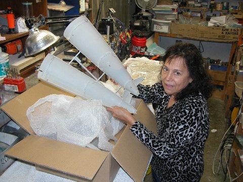
The plastic model that ate the Philippines
Ellie unpacking our copy from the first set of 1/72 SKIPJACK test shots out of China, forwarded to us from Moebius. This model submarine is big.
OK, truth in advertising time: Ellie’s a little five-foot Filipino type, so the model appears larger than in real life. However, balancing that, I’m a six-foot-something, nasty, planet-destroying, meat-eating, baby-seal-thumping, European type and this kit is big to ME! It’s a big improvement over the mock-up. So far, so good …
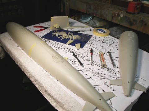
Test shot begins run through the gauntlet
With an example of the first test shot series in hand (at last some honest to goodness polystyrene to fondle) I bounced the dimensions and form of the kit parts against my documentation – the primary source being the excellent Greg Sharpe drawing. You see a hash-marked area atop the upper hull where, for some unknown reason, the initial tooling produced a ‘dip’ just aft of the after deck flat. First gig identified. There would be more.
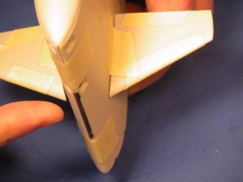
Too blunt edge on the sail needed correcting
The fillet between the sail and the long, skinny diesel exhaust fairing needed changing. Also, the leading edge and trailing edge of the sail were found to be too blunt. More items for the Chinese tool-and-die guys to fix.
A remarkable example of excellent tool design and execution is the propeller: The Chinese made a spot on reproduction of the propeller master I sent them; the rendering of it, in polystyrene above, is a perfect twin. Of particular note is capture of the complicated curves in a tool that avoids high draft angle.
Ingenious solution to prop part engineering
The solution our tool-makers came up with was to make the majority of the hub and blades as a single part, with the base of the hub – those areas under the blades – as another part. These two sub-assemblies fit together with a surprisingly tight fit requiring little filling by the kit-assembler. I am most impressed with how the Chinese solved the propeller part fabrication problem.
Frame extensions under snorkel fairing need some ‘tweaking’
One of the things I did to the mock-up was to add the frames within the diesel exhaust fairing. That feature, now incorporated in the test shots, came out fine. However, the outboard portions of the ribs that project down – and seen through the long-running limber slit between hull and fairing – were flush with the outside of the fairing. They should have been indented to the surface of the fairing by about a sixteenth-of-an-inch.
Shape issue with snorkel fairing
I marked them, and added this item to the list of tool modifications.
The after end of the diesel exhaust fairing was too blunt. I added that to the list’.
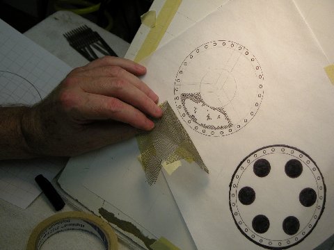
Bill Rogers, a fine scratch-builder, found a picture of an S5W powered submarine in dry-dock. You see a print of that in the below picture. Its the only good look I’ve seen of the gratings associated with that type plant’s main condensers.
(My inspections of the same type gratings on my boat, the DANIEL WEBSTER, way back in the day, don’t count as it was all done by feel.
At one time I was one of the two boat Diver’s who did security swims ball-valve greasing, and flange work in filthy, nearly opaque harbor water).
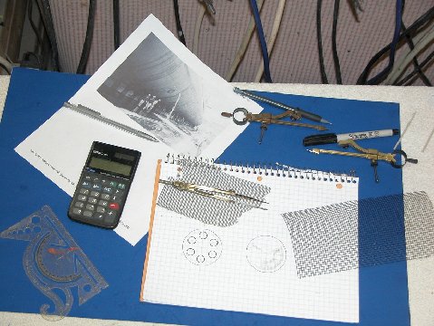
Working on underside grating details
Pictured is a preliminary drawing to help me resolve the projected shape of the two types of main condenser gratings we needed PE parts for. The picture above was my only document to work from, so several attempts were made till the things started to look right on graph paper. I knew the diameter of the gratings thanks to the BUSHIP General Arrangement drawing, so all I had to do was make the holes and bars across the face of the respective gratings look right. Once happy with the look, I produce a proper piece of artwork, five times the eventual part size, and send it to the Chinese for processing and manufacture of the PE kit parts.
Drafting the grating PE artwork
Preparing the over-sized artwork representing the SKIPJACK’s MSW suction and discharge gratings. These went to China where they were scanned and that file used to produce the masking needed to make production stainless steel PE parts.
I’m old-school when it comes to drafting, no CAD for me – you don’t get totally involved in the project if you simply push a mouse around a drafting menu. No, dammit! In my world you get your hands dirty; you become intimate with the task; involve yourself physically with the work. That’s the only way you can truly capture into you little brain all the nuances of the subject you’re attempting to represent.
What the hell are we now, a bunch of mindless, automatons; only able to push buttons and respond to formulated stimuli?! I see no craft in computer aided drawing or machining! What’s creative about punching up preordained code? We don’t have real Machinist’s any more … just over-paid bit-changers and chip sweepers. (Picture me running in circles with my hair on fire!)
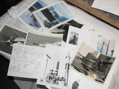
Small part of the SKIPJACK reference file
A quick look at just some of the photos used to help flesh out details as I worked the mock-up and checked the test shots (yes, there were more than one set test shots that ran the gauntlet – we kept at it till things were as right as we could get them). All from my rather massive SKIPJACK folder. Research and adherence to the things research reveals is everything in this game.
I’m a reasonably skilled draftsman. Apprentice level, but adequate to my needs. Unlike my junior high school peers – the hoods, idiots, booger-pickers, and jock’s – I rubbed shoulders with in shop class, I paid attention and enjoyed learning about and practicing the Crafts. Training that has served me to this day.
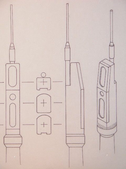
Finished ‘scope drawing
The first test shot periscopes were elemental of form, not at all suitable for a model of the SKIPJACK’s size. To help the Chinese work out better detailed periscope heads I prepared the above orthographic and isometric projections. The second test shot came in with scope heads very close to what I illustrated. There were two types on the SKIPJACK. I’ve shown here the Type-15 ‘search’ periscope which featured a range-only radar antenna. Yeah, I’m a detail freak. I blame Ben Guenther!
Tappan Junior High School’s shop class (mandatory for all boys) was divided into three sections: Wood Shop, Metal shop, and Drafting. Wood Shop taught by a fellow class mates Dad, a rather handy fellow around the benches; Metal Shop taught by a tough little ex-Army booze-breath who really knew his stuff, and could weld anything to anything else; and the Drafting instructor was an old, skinny, well dressed, exacting, gentleman who took no sh*t from ANYONE (he managed, unlike other school staff, to keep the hoods in line).
How come I remember this ancient stuff but not my kids birthday?!….
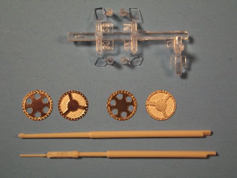
Photoetched grates, clear ‘lights’ and periscope detail parts
Over the course of a three-month evaluation process we went through two test shot cycles. The work above is from the second test shot I got for examination. By this time, as two examples, we had refined the look of the two styrene optical periscopes and form of the photoetched (PE) main sea water suction and discharge gratings.
We all have Bill Rogers to thank for unearthing that photo of the MSW gratings. Nowhere else have I found a definitive look at those main condenser openings, unique to boats employing the S5W nuclear plant. Though the dry-dock picture is of a Polaris boat, it (as so many other American, and even one British, early nuclear powered submarines), like the SKIPJACK’s, made use of the same S5W plant. So, it’s a logical expectation that the MSW gratings seen on this Boomer were very similar to those on the SKIPJACK boats. Anyone out there who can make a liar out of me? Let’s see what you got!
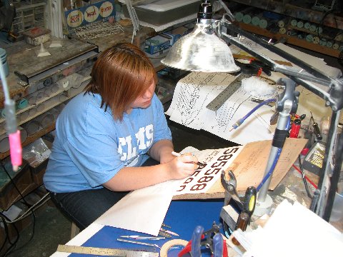
Apprentice hard at work on ‘inport’ sail numbers – ‘old school’
There’s something to be said for slave-labor! I’ve found that staff productivity is directly proportional to the voltage applied. As the SKIPJACK work turned into a grind I noted that my Granddaughter had been getting into manga sketching big-time and was showing some talent. So, never one to waste an asset, I dragooned her into the shop to help me with the decal and PE graphics. She told me that she could punch it all out on a computer. Hell, no, I said. Regardless, she snuck out when I was involved in something else, got to the computer and took it as far as finding the correct fonts somewhere in digital-land. I put a screeching halt to that! Here, recaptured, Rose – an ankle chained to a leg of the desk – is inking the decal artwork.’ What’s with the attitude, Rose!? … give us a smile!”
As with PE artwork, its good practice to render the decal artwork several times the eventual size of the finished product (PE or decal contact negative/positive). As the artwork images are reduced in the process camera – or, these days, scanner – image density increases and becomes ‘tighter’. Rose is working to a five-to-one ratio, if I remember correctly.
Trackbacks:The research I did in support of the Moebius Models 1/72 SKIPJACK kit resulted in a rather thick folder of plans (both BUSHIP based and private sources), photographs, tables, and news clippings.
Pull up a chair, boy’s and girl’s, it’s Story Time with Uncle Dave:
In the early ’70’s while working as an exhibit maker (and toilet-scrubber) at the Submarine Force Library and Museum, I was tasked with bagging for ‘burn’, filing cabinets full of American submarine plans, the Booklet of General Plans and Docking and plans dating back to the A-Class boats (up to and including the GUPPY converted TENCH class boats.) Those hard copies, blue-prints if you will, were being replaced by micro-film captures of the documents, and the museum wanted our old, bulky, dusty prints out of the way. It was all unclassified. Hmmmm …. what to do?
As if by magic, most of that trash wound up at my home. Unknown to me, at a different location on the upper base, some of the general arrangement post war diesel and older nuclear submarine plans had also been declassified and scheduled for disposal. Enter Jim Christly, fellow model builder, canvas artist, historian and well-known author. Jim also worked at the upper base and in his travels found where those plans were and – knowing my keen interest in all things SKIPJACK – one day stopped by my workshop/dungeon and tossed a set of downgraded SKIPJACK documents in my lap. Wow!
Many years later Greg Sharpe (one of the finest R/C model submarine fabricators on the planet) had set up a business producing and selling builder’s plans of modern submarines. He had always been very helpful with my various researches, so I reciprocated and shared with him the SKIPJACK file which contained good quality copies of the BUSHIP drawings. Eventually, Greg produced an excellent, well formatted set of drawings.
Long story short: Greg’s drawings were the backbone of the package sent to China to get the SKIPJACK kit tooling made. Accompanying the research package was a completed and well detailed 1/96 scale SKIPJACK model intended for scanning as the basis to generate a CAD file.
After Moebius committed to the project of producing a 1/72 SKIPJACK kit, I took on the assignment of lead-man. My job being to gather and send off to Dave Metzner, the Moebius product development guy, a package containing all the information the Chinese needed to render an accurate kit.
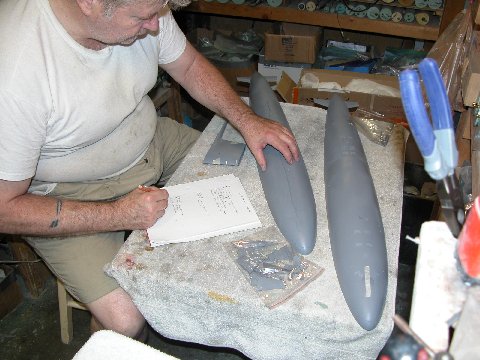
Checking the 3D printed mockup
I’m pictured here surveying the mockup they sent. That mockup, 3D printed in accordance to the materials I sent them, had major problems! That list you see me compiling grew to an eventual three pages of things that had to be fixed.
One of the many faults found on the mockup identified here: incorrect location of the transitioning fillet between the diesel exhaust fairing and the sail sides.
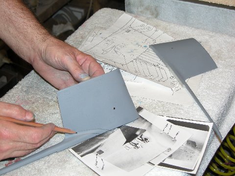
Sail review work
Like all other anomalies found on the mockup, I performed a re-contouring action to get the mockup parts as close to documentation as I could. Note the pictures of a SKIPJACK sail under the work – sometimes photos are the only way to go when the plans are not enough. Such was case here: The plans showed only the plan and profile of the fairing-sail interface, but no indication as to the radius and sweep of the fillet between the two structures. This is when you make use of your well trained eyes and good old ‘computer number-one’.
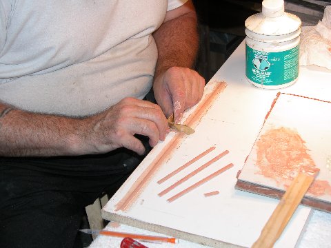
Screed technique for forming half mast master parts
In parallel with mockup correction I set about the task of working up masters to enhance the look and function of the many retractable masts that fit within the SKIPJACK’s sail. The proposed kit parts had masts long enough to project atop the sail in their ‘raised’ positions, but only had enough material in the bases to fit sockets in the top of the sail. Not suitable for a practical retraction/extension mechanism. To address this, first a linear screeding tool was used to form half-mast masters from a two-part automotive filler. The brass screeding blade between my hands has a fence that rests on the outer edge of this molding-board, I lay down some catalyzed filler on the board, under the opening cut into the blade of the screeding tool – that opening representing 1/2 of the desired mast section. As I pull the blade lengthwise across the mold board, the opening in the blade forces the filler to adopt the shape of the half-mast. The mold board was precoated with mold-release wax to aid a clean break-away of the half-mast master off the mold-board after the work was done. The master was broken into two equal length pieces, and glued together, face-to-face, making a complete mast master.
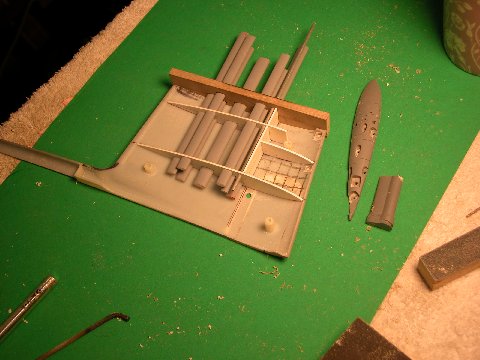
Sail detailing masters
This is how far I got with the retractable masts and bridge and lower platform masters before being informed that this work, if it were turned into tooling and kit parts would radically increase the price of the kit. So, this work sits in a box awaiting the day I have time to produce aftermarket sail mast, scope, antenna, and sail interior detailing kits. If no interest materializes, then this stuff will join two shed fulls of similar crap for my estate executor to haul to the local land-fill. (I don’t like to think about it.)
I don’t know what the hell happened in China with the propeller, but, the mockup they sent was horrible! No good reason for it: I sent them a 1/96 sample of the SKIPJACK wheel for scanning. What happened?! Anyway… after examination and rejection (at considerable velocity, against the far wall) of the mockup propeller, I made up my mind to build a physical 1/72 propeller for them to scan. It being my hope that they would produce a CAD file off the new propeller from which to eventually drive a CNC machine for tool fabrication.
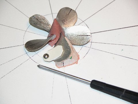
Propeller correction master in construction jig
Here’s the build-up of that propeller master. It’s my practice to make one propeller blade master; pull a high-temperature RTV tool from that; cast up the required number of blades; then assemble those blades about a RenShape hub mounted on a blade assembly jig, securing them with CA mixed with baking soda. Me much smart!
The amount of corrective work required on the hull necessitated creation of this securing/layout fixture.
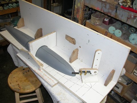
Securing/Layout fixture with 3D mockup in place
It would permit me to accurately lay down radial lines, longitudinal lines, and to loft – directly off a scale drawing of the SKIPJACK – engraved line locations. The pen loaded surface-gauge, running along the vertical, longitudinally running board, marks off longitudinal lines. The surface gauge mounted to the transverse vertical board lays down radial lines – such as the station/ section lines spaced evenly along the length of the hull. Proper layout is everything in model making – if you don’t establish and follow your datum points, lines, and landmarks, you will never achieve reasonable symmetry. (Sounds like something Buddha would have said.)
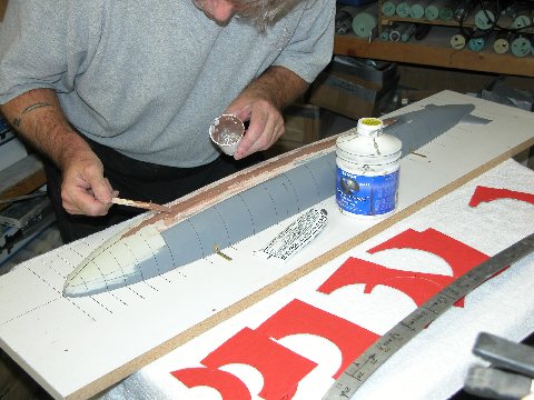
Applying 2-part filler to correct upper contour
Here is the securing/layout fixture partially disassembled to better access the mockup for re-contouring. Note the cardboard station templates in the foreground – used to check my work as I re-established the correct radius to the erroneously flat portions of the mockup. I lay down some filler, let it cure, then worked it, a bit at a time, with a course file, constantly checking the contour with the templates.
The only non-round portions of the SKIPJACK hull are two deck flats, one ahead, and one astern of the sail – flat to give assured footing to line-handlers and other men on deck.
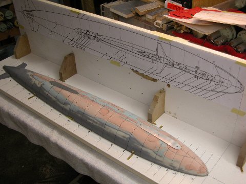
Aluminum ‘flats’ screwed to mockup prior to applying filler
I elected to first get the entire upper hull back to round with filler (no corrective actions required to the lower hull), and only then to build up the flats. The two flats were re-established by screwing down suitably shaped .030″ thick aluminum deck flat forms upon the hull and building up filler between the hull and form edges. See the long lines either side of the sail on the drawing taped to the vertical, longitudinally running board? Those lines simply identify the anti-skid outline. However, I failed to inform the Chinese of that and they interpreted the lines to denote a flat, so that’s how the mockup hull came out, one long flat to the deck, not two smaller ones. My mistake – not properly explaining this feature in the cover letter that accompanied the documentation I sent – cost Moebius both time and money. Lesson learned!
Note how I used different colored hardener in the filler mix to identify high and low points as I applied and filed back the filler as I restored the upper hull back to a round section.
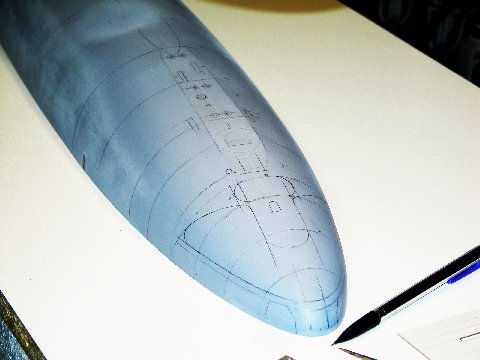
Penciling in the engraving marks to restore lost detail
Before I could scribe in all the detail lost when I re-built the top of the upper hull, I had to first lay out, in pen and pencil, the position and shape of the eventual engraved lines. The securing/layout fixture made that chore a quick and accurate one. You can make out the forward flat very well in this shot.
After layout, I scribed in all the lines lost during the hull re-build. Some of the engraving to be performed represents the upper sonar dome window, upper torpedo tube shutter-doors, forward escape buoy, escape trunk hatch, torpedo loading hatch, reversible cleats, salvage plates, capstan head, etc.
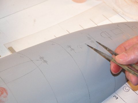
Transferring landmark points to model in prep for engraving
I also failed to provide the Chinese with any information that identified the point of rotation of the full-flying control surfaces. So, they took their best guess as to center-of-rotation for each control surface … and got each and every one wrong. Not a big deal to static kit-assemblers, but for those who would go on to assemble the kit for R/C operation, control surface center-of-rotation position is a vital consideration both for scale looks and flutter avoidance.
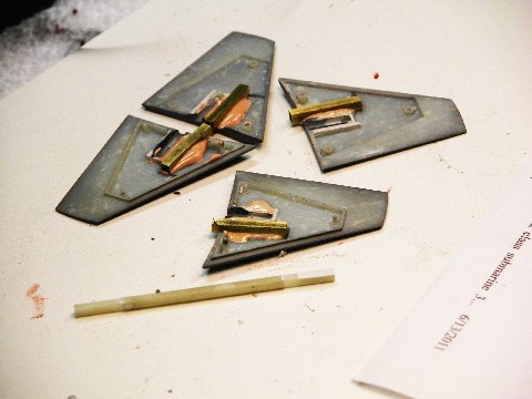
Re-engineering control surface pivots for practical (and accuracy) considerations
So, I modified the mockup control surfaces with properly located foundations to accept the control surface operating shafts. I should have been on top of this from the beginning of the project, but missed it. Bad.
Finally, I got all the fixes I could identify incorporated into the Chinese mockup. Here it’s been test fit together, ready for shipment to Moebius who got it just in time to make the Chicago IHobby show last year. At this first public showing of the Moebius Models 1/72 SKIPJACK, it was well received.
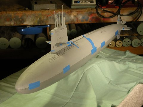
Corrected 3D mockup test fitting – looks good!
After the show, the corrected mockup was shipped to China for laser scanning, which produced a file suitable for CNC cutting of the production tools. The writing you see on the mockup (looks like tiny vents here) is there to identify the corrected areas, just to make sure my changes would be identified and the re-contoured areas recorded into the software.
Shots of the mockup at the IHobby show can be viewed along with comments at:
Trackbacks: