This series of images is of the SH-2F airframe (BuNo. 149026) being used as a ‘gate guard’ at NAS Norfolk, Virginia. Most were taken in 2013 though the more ‘colorful’ paint scheme was from a couple of years earlier. Keep in mind, this is a derelict bird, missing many minor parts (such as the hydraulic brake lines leading from the fuselage to the landing gear) but still the pictures are useful for structural details. I have tried to note any detail issues the best I might but here are some general notes:
- The landing gear are missing a lot of parts including the brake rotors, calipers & pressure lines. Also missing are all the sensors and associated wiring.
- All original stenciling was not applied to this gate guard.
- No interior pictures are available since all the windows were painted black.
- Wheel well images require careful examination; image labels describe the locations.
Many of the images show a folding ruler as a dimensional reference. A few show an adhoc reference in the form of my 3-7/8″ long by 2-0″ wide LG Shine phone. Look for a further walkaround for the generally similar HH-2D held at the American Helicopter Museum & Education Center in West Chester, Pennsylvania (click HERE.) (To see images full size, right-click and select “View image” or equivalent for your browser type.)

Port drop tank fuel filler cap – normally painted red

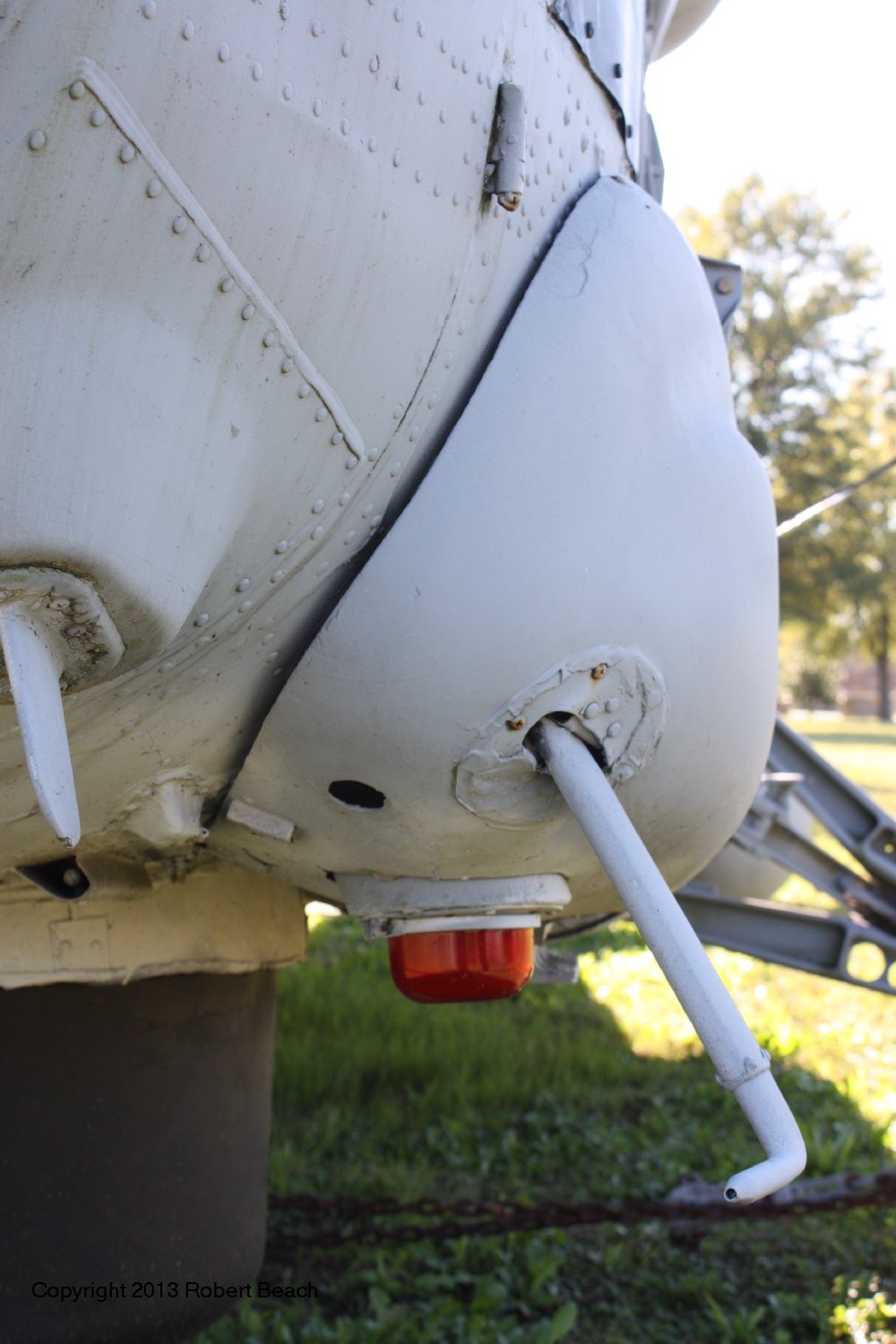
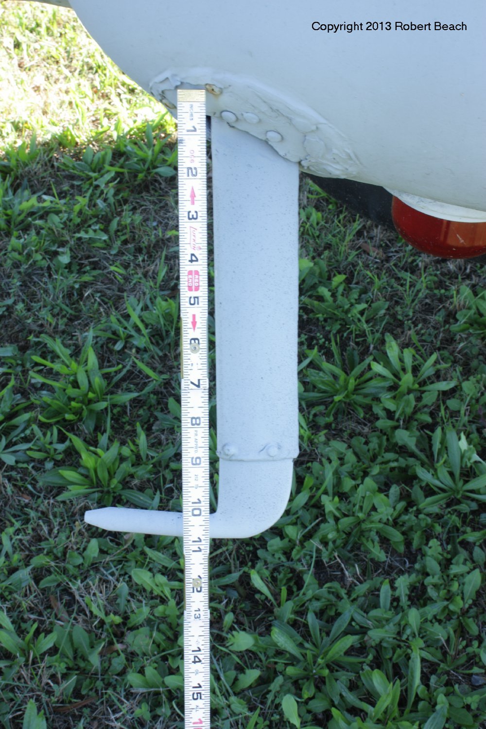
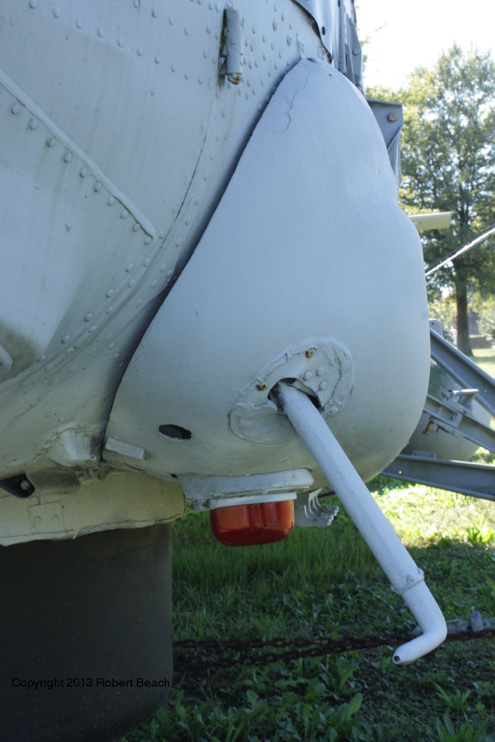
Port side gear fairing – note the marker smoke float ‘clips’ behind the red strobe light

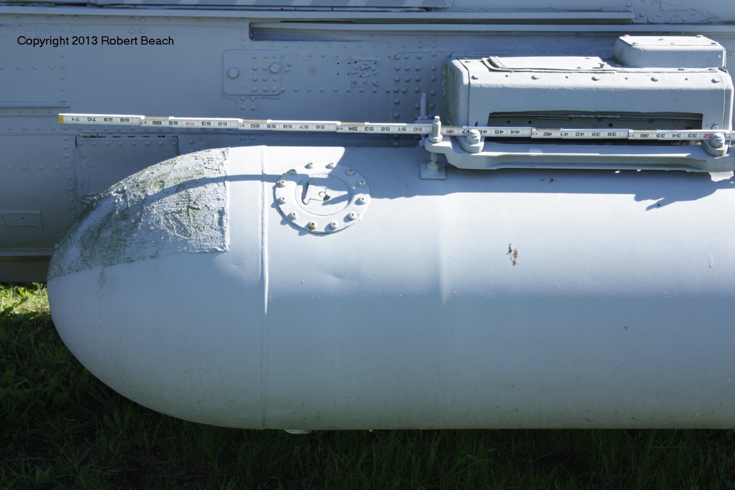
Starboard drop tank aft end – note missing connections to tank level sensor

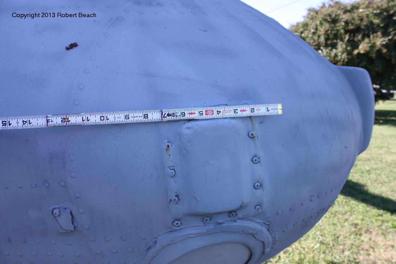
Port drop tank aft end – note the non-skid ‘step patch’

Port side doppler altimeter antenna fairing

Note typical use of ‘potting compound’ sealant – applied liberally throughout the airframe to prevent corrosion

Starboard side view showing a couple of the hand holds used by aircrew to clamber up top for preflight and maintenance

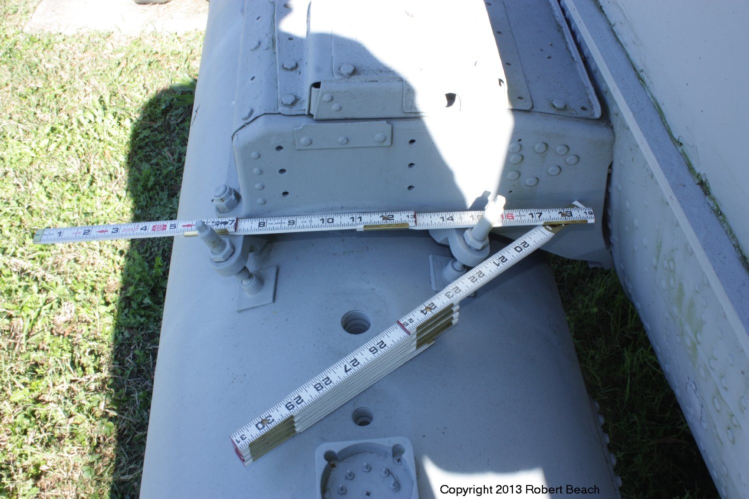
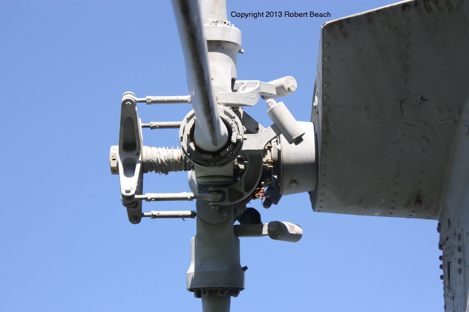
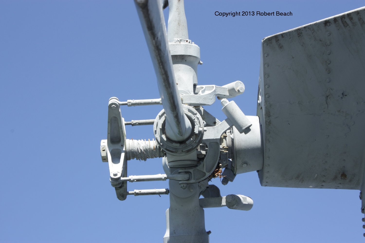
Magnetic Anomaly Detector (MAD) gear pylon – only on starboard side and separate from the fuselage hardpoint

Obviously the drag ring is damaged – this is a metal version, there was also a version made of expanded styrene foam

The rod protruding about midway along the MAD ‘bird’ is hooked when it is reeled up and locked. The reel & winch is inside the fairing, which includes a ‘cut gun’ device to cut the cable in case the bird hits something (like the ocean!)

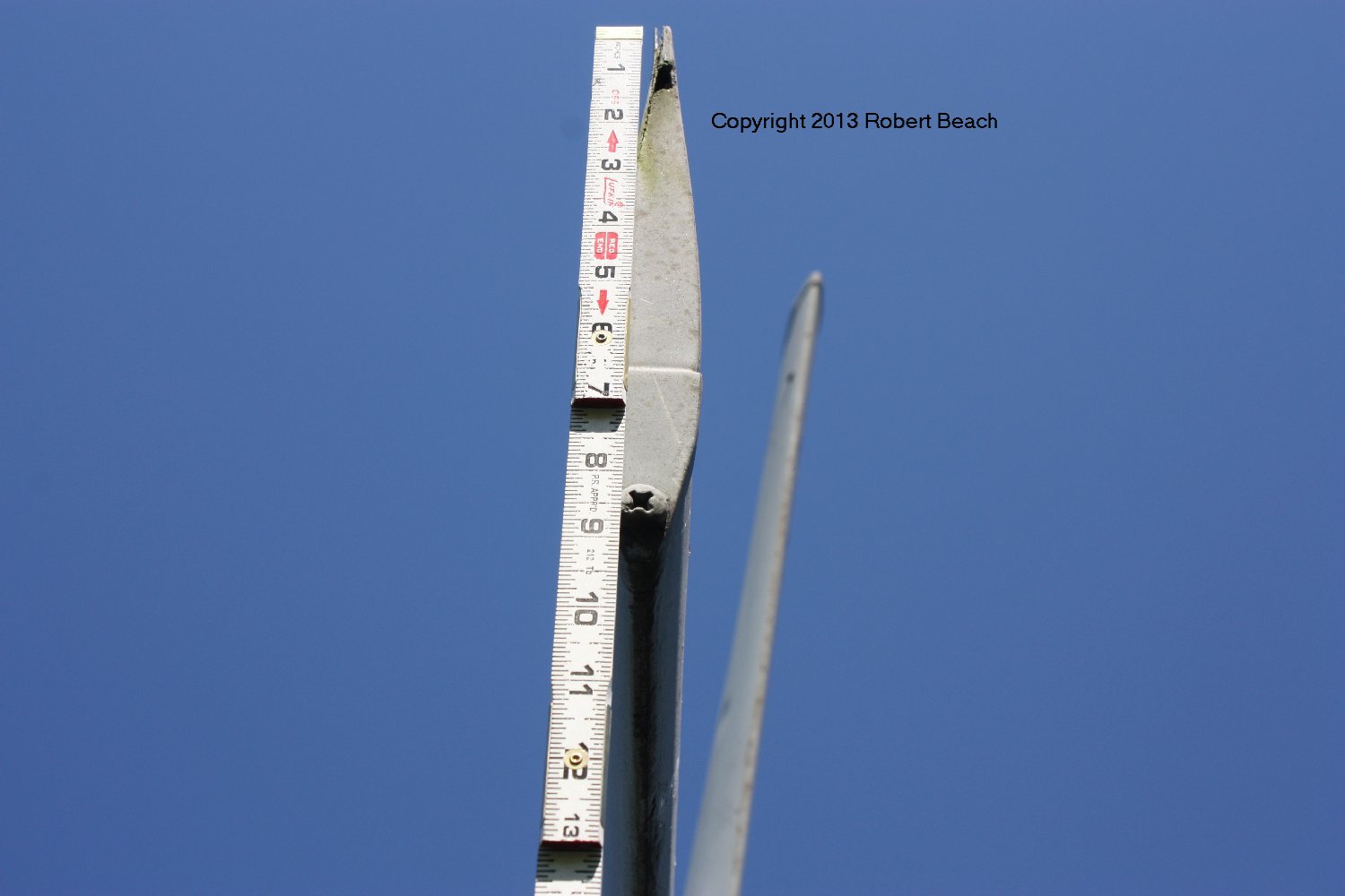
These stickers were placed by the ‘paint crew’ when the airframe was painted in its colorful scheme – unfortunately, I failed to take a picture of the location

The hook ‘faces’ forward, which is to the left in this image
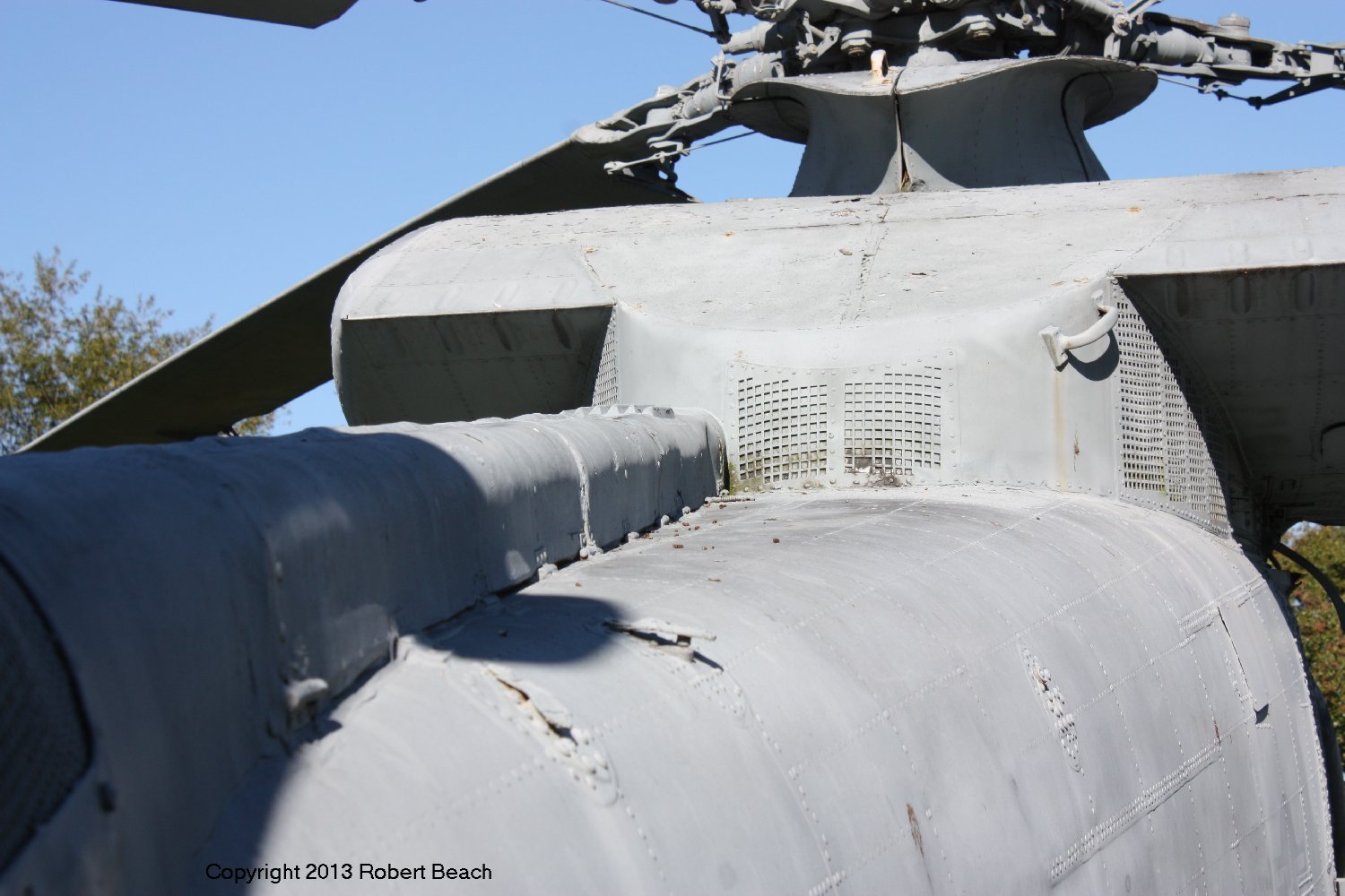
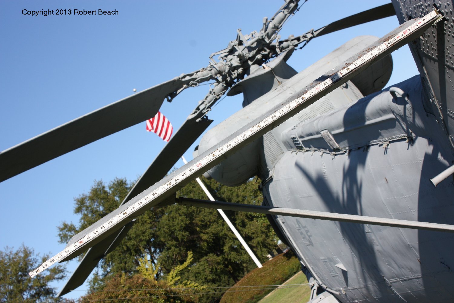
Another view of the transmission fairing. Underneath is the combining ‘box’ that takes the power from both engines and the splits it to both the main & tail rotor. Note how the tail rotor (mounted externally to the fuselage under its cover) comes out offset to the port side.

Being relatively compact, the ‘Hookie Took’ (who-key two-kuh) did not have a folding tail. Note the fairly ‘rugged’ finish of the skin which is not entirely due to the plane’s ‘gate guard’ status. The small hole near bottom right side is missing the flexible plug & retaining flap as visible on the port near the top right. These are where the rotor blade gear struts mounted when the blades were folded.

This view shows the retractable foot pegs used along with the upper hand-hold to conduct preflight inspections of the tail rotor and the TR shaft gearboxes, which are visible through the screen mesh panels. Again note the tail’s asymmetry so typical of much of the Seasprite.

Good view of the tail ECM antennas. These provided data to the pilot regarding emissions of “interest” illuminating the helicopter.

Four bladed tail rotor; control inputs were applied via a rod through the hollow drive shaft.

One of the two types of vents found on the tail rotor cover that helped provide cooling airflow to the shaft bearings. Note the small ‘slide’ catches (along the port side only) that allowed for preflight inspection of the shaft and bearings when the hinged cover sections were opened to starboard.

The other type of vent (plus more catches.)
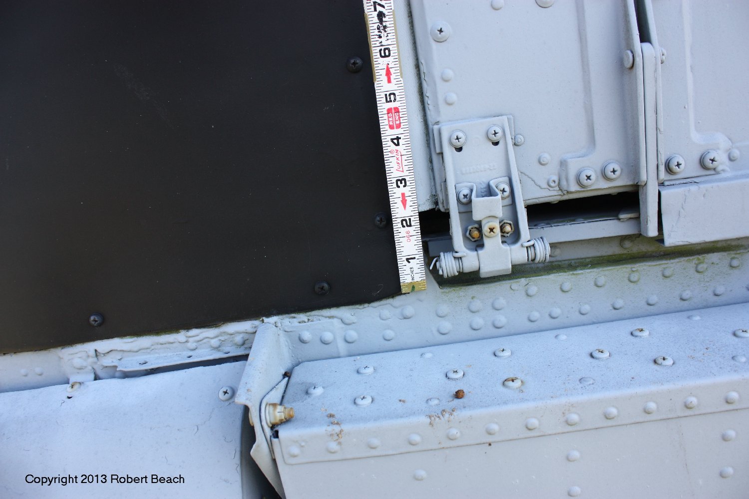
View shows the port side slide and latch at the forward bottom of the pilot’s door. The nose transparency has been replaced with a black painted metal panel.

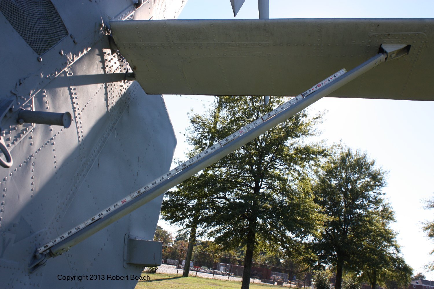
Tip of the port horizontal tail surface. These were not moving surfaces and didn’t fold though they could be removed if necessary.

Port stores hard-point which was of a standard configuration for carriage of drop tanks, torps or other ordnance.

A somewhat awkward angle…


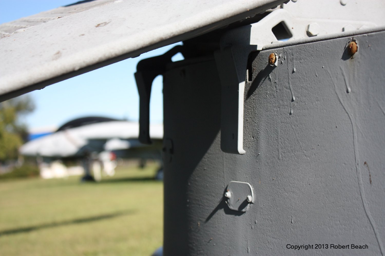


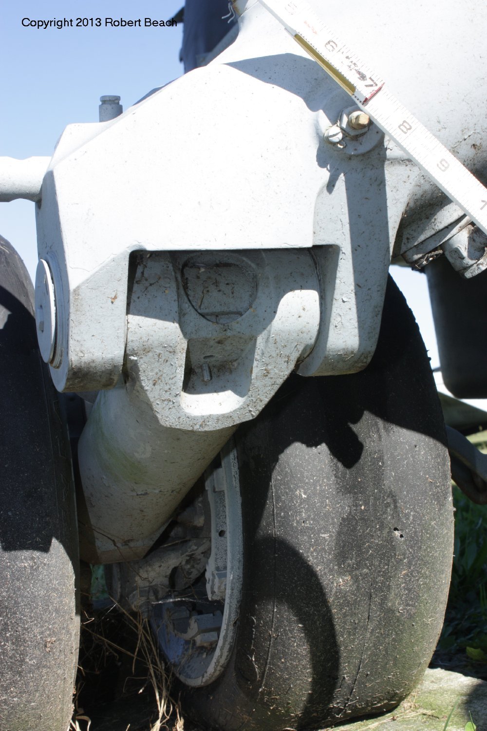


As noted, all the hydraulic lines, electrical wiring, etc. has been stripped from this example’s landing gear. This does provide an uncluttered view, however. The function of the bracket with two bolts hanging from the lower fuselage mount point is unknown and may be non standard for an airworthy aircraft.

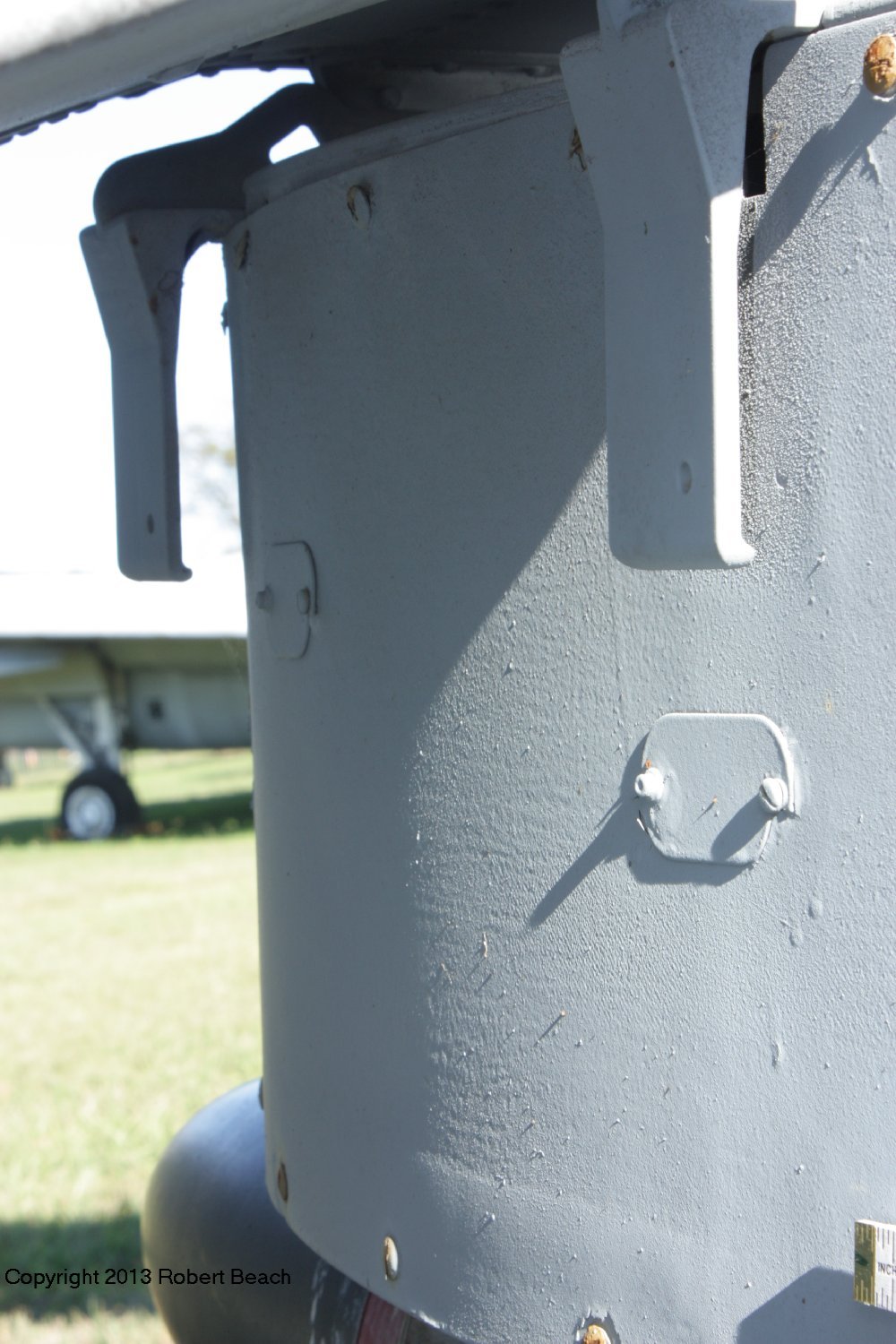
Again, the function of this hanging bracket is unknown

Tail wheel tire was looking better in 2013… the tail gear castored but could be locked in fore & aft position by the spring ‘wrapped’ rod at its forward top section.

This old fitting at the front of the starboard gear fairing is left over from the early single engine versions. It is where a hoist boom was mounted so the second pilot could operate the hoist. The rescue hoist was moved to a position about the starboard crew door on the twin engine versions because now an aircrewman was available to run the hoist.

The colorful ‘gate guard’ paint scheme. Note the black non skid areas are more visible than the later ‘all grey’ scheme. The ‘bump’ below the star-n-bar is where a static pressure port is located (above the little ‘shelf’.)

Mirror was used to observe the hoist operation – not to ‘check six’!

Stores hard point is missing a cover panel

Fuel filler necks used for ‘gravity feed’ filling of tanks. Missing the fuel caps.

This latch mechanism is ‘busted’. Doors and tracks were a maintenance headache at times…

The foot steps are visible here, covered with screwed plates to prevent visitors from clambering up topside.

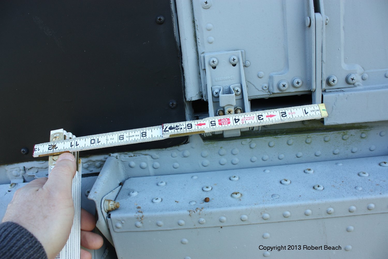
This is the single-point pressure refueling port – with its cap – located on the starboard side aft of the twin filler ports. This was used for ‘hot refueling’ (fueling with the engines running.)

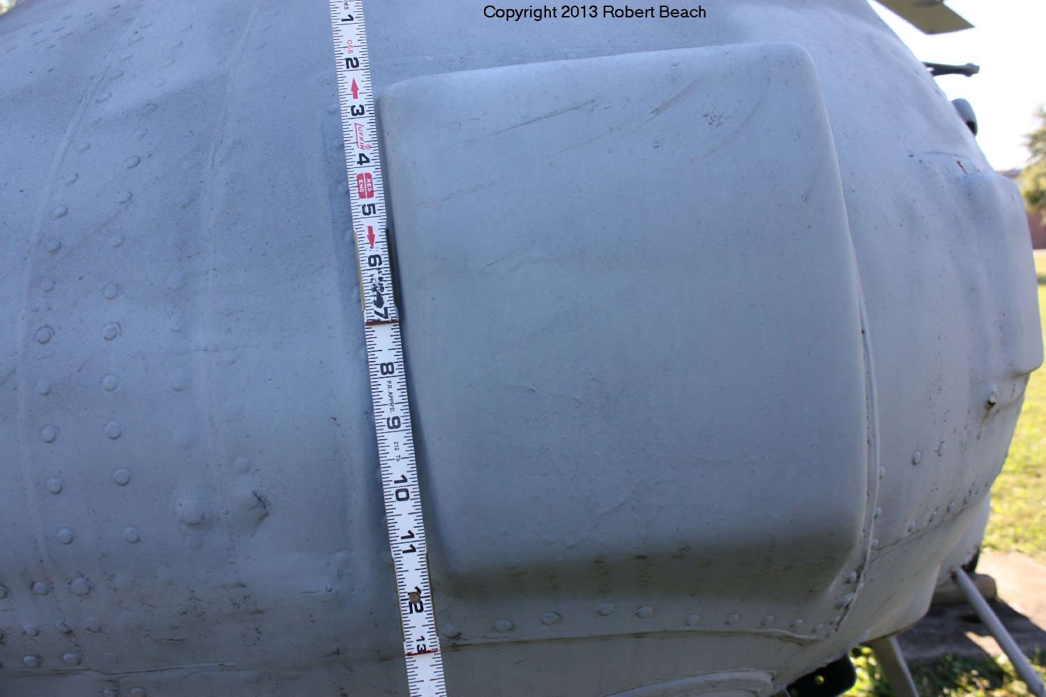
The prominent vertical ‘seam’ visible in the cowling just below the rotor is typical. The fairing was in two halves that hinged open to the sides to allow access to the aft of the main rotor transmission.

Search radar dome from starboard side wheel well – note ‘notch’ for landing gear retraction clearance. This was due to dome being offset to starboard.

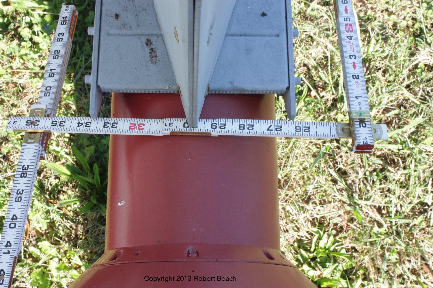
Front view shows how the radome is offset to starboard of the centerline.

SH-2 ties were highly pressurized with nitrogen and actually were an explosive hazard. They were inspected carefully…


4 Responses to SH-2F Seasprite Helicopter