Report to the Cabal: Part 3
Today the chronology of events in the production of an injection-formed plastic model kit goes something like this:
1. Lead-man is assigned, research is completed, and documents and scanning models (optional, but desired) are scanned and reduced to a CAD file.
2. That file used to create a stereo lithographic 3D mock-up, or proof model, which is sent to the client for approval/correction.
3. The corrected mock-up is returned to the manufacturer with needed changes identified, the CAD file updated and converted to CNC code and (in a flurry of metal chips) the injection forming tools are cut and clamped into a production injection forming machine.
4. The tool clamping system is fine-tuned after the factory tool & die guys examine the first shots out of the machine. They are informed by the physical condition of the shot (symptoms shown): Does the machine achieve a complete fill of the tools cavities (temperature, pressure and channel geometry)? Are the two tool halves in alignment (unregistered halves to a shots tree)? Is an even distribution of force applied throughout the flange area of the two tool halves during the shot (flash)? And do all the test shot plastic parts fit without misalignment between them (machine cycle time)? After the clamping system is dialed in, cycle rate established and other working parameters properly set, then good quality test shots can be produced consistently. Samples can then sent to the client for critique.
5. Corrections to the tooling are performed to satisfy the client identified errors found on the test shot parts. This likely requires more cutting in the tool and may also involve weld build-up and re-machining.
6. Box-art, instructions, packaging, decals, PE and other tasks are reduced to production steps, and all items integrated into a complete kit, ready for a ride on a big container ship. (The ideal – most efficient – source of manufacture is one equipped to perform all injection-forming, printing, PE work, and other tasks in-house. Unfortunately, no such facility exists in America today).
So, as far as Moebius is concerned, the test shots received are for validation of fit, part quality and accuracy between the prototype and the assembled kit’s representation. The customer examines the test shots and either okays the product or generates a list of the tooling changes needed. Sometimes a test shot is handed out as a review kit to help chum the waters.
Several months passed until I got my grubby hands on a test shot. The box arrived at our door with a thump. But to me, it was the sound of the last round bell of a 12-round fight I was winning on points but wanted a knock-out. Ellie brought the box into the shop, plopped it on a work-table and gave me one of those patented side-wise grins, and handed over the box-cutter. Show time! I paused a moment to reflect.
Wanna know what happens to a group effort when the lead-man gets it wrong? Let’s see … hmmm… Think, Plan-9 From Outer Space. Think, Titanic. Think, Edsel. Think, Little Big-Horn. Think, Hindenberg. And think, I-53. Bad Ju-Ju when the lead-man gets it wrong. I slit the top of the box from China …
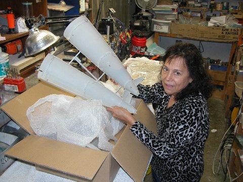
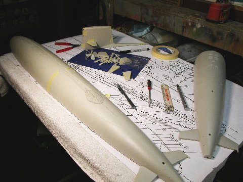
Ellie unpacking our copy from the first set of 1/72 SKIPJACK test shots out of China, forwarded to us from Moebius. This model submarine is big.
OK, truth in advertising time: Ellie’s a little five-foot Filipino type, so the model appears larger than in real life. However, balancing that, I’m a six-foot-something, nasty, planet-destroying, meat-eating, baby-seal-thumping, European type and this kit is big to ME! It’s a big improvement over the mock-up. So far, so good …
With an example of the first test shot series in hand (at last some honest to goodness polystyrene to fondle) I bounced the dimensions and form of the kit parts against my documentation – the primary source being the excellent Greg Sharpe drawing. You see a hash-marked area atop the upper hull where, for some unknown reason, the initial tooling produced a ‘dip’ just aft of the after deck flat. First gig identified. There would be more.
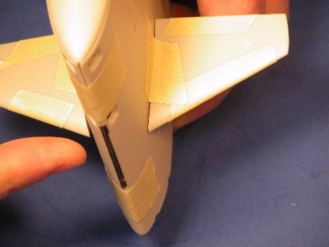
The fillet between the sail and the long, skinny diesel exhaust fairing needed changing. Also, the leading edge and trailing edge of the sail were found to be too blunt. More items for the Chinese tool-and-die guys to fix.
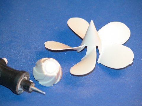
A remarkable example of excellent tool design and execution is the propeller: The Chinese made a spot on reproduction of the propeller master I sent them; the rendering of it, in polystyrene above, is a perfect twin. Of particular note is capture of the complicated curves in a tool that avoids high draft angle.
The solution our tool-makers came up with was to make the majority of the hub and blades as a single part, with the base of the hub – those areas under the blades – as another part. These two sub-assemblies fit together with a surprisingly tight fit requiring little filling by the kit-assembler. I am most impressed with how the Chinese solved the propeller part fabrication problem.
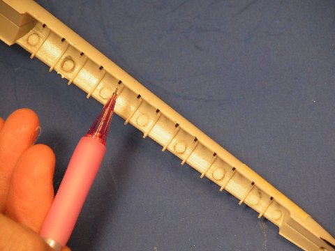
One of the things I did to the mock-up was to add the frames within the diesel exhaust fairing. That feature, now incorporated in the test shots, came out fine. However, the outboard portions of the ribs that project down – and seen through the long-running limber slit between hull and fairing – were flush with the outside of the fairing. They should have been indented to the surface of the fairing by about a sixteenth-of-an-inch.
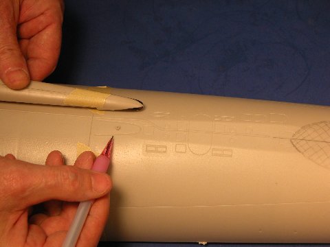
Shape issue with snorkel fairing
I marked them, and added this item to the list of tool modifications.
The after end of the diesel exhaust fairing was too blunt. I added that to the list’.
Bill Rogers, a fine scratch-builder, found a picture of an S5W powered submarine in dry-dock. You see a print of that in the below picture. Its the only good look I’ve seen of the gratings associated with that type plant’s main condensers.
(My inspections of the same type gratings on my boat, the DANIEL WEBSTER, way back in the day, don’t count as it was all done by feel.
At one time I was one of the two boat Diver’s who did security swims ball-valve greasing, and flange work in filthy, nearly opaque harbor water).
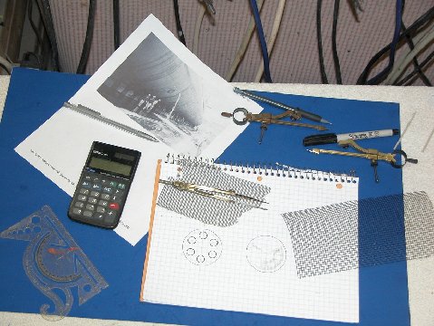
Working on underside grating details
Pictured is a preliminary drawing to help me resolve the projected shape of the two types of main condenser gratings we needed PE parts for. The picture above was my only document to work from, so several attempts were made till the things started to look right on graph paper. I knew the diameter of the gratings thanks to the BUSHIP General Arrangement drawing, so all I had to do was make the holes and bars across the face of the respective gratings look right. Once happy with the look, I produce a proper piece of artwork, five times the eventual part size, and send it to the Chinese for processing and manufacture of the PE kit parts.
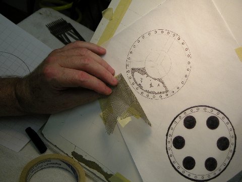
Drafting the grating PE artwork
Preparing the over-sized artwork representing the SKIPJACK’s MSW suction and discharge gratings. These went to China where they were scanned and that file used to produce the masking needed to make production stainless steel PE parts.
I’m old-school when it comes to drafting, no CAD for me – you don’t get totally involved in the project if you simply push a mouse around a drafting menu. No, dammit! In my world you get your hands dirty; you become intimate with the task; involve yourself physically with the work. That’s the only way you can truly capture into you little brain all the nuances of the subject you’re attempting to represent.
What the hell are we now, a bunch of mindless, automatons; only able to push buttons and respond to formulated stimuli?! I see no craft in computer aided drawing or machining! What’s creative about punching up preordained code? We don’t have real Machinist’s any more … just over-paid bit-changers and chip sweepers. (Picture me running in circles with my hair on fire!)
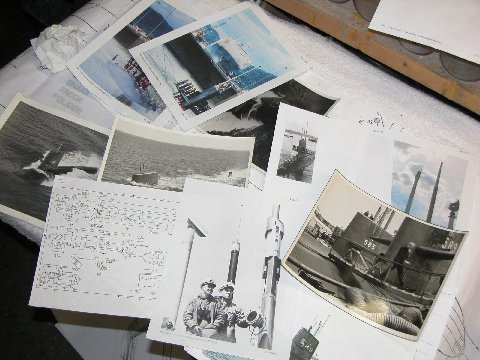
Small part of the SKIPJACK reference file
A quick look at just some of the photos used to help flesh out details as I worked the mock-up and checked the test shots (yes, there were more than one set test shots that ran the gauntlet – we kept at it till things were as right as we could get them). All from my rather massive SKIPJACK folder. Research and adherence to the things research reveals is everything in this game.
I’m a reasonably skilled draftsman. Apprentice level, but adequate to my needs. Unlike my junior high school peers – the hoods, idiots, booger-pickers, and jock’s – I rubbed shoulders with in shop class, I paid attention and enjoyed learning about and practicing the Crafts. Training that has served me to this day.
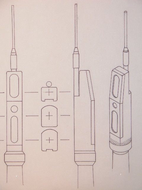
Finished ‘scope drawing
The first test shot periscopes were elemental of form, not at all suitable for a model of the SKIPJACK’s size. To help the Chinese work out better detailed periscope heads I prepared the above orthographic and isometric projections. The second test shot came in with scope heads very close to what I illustrated. There were two types on the SKIPJACK. I’ve shown here the Type-15 ‘search’ periscope which featured a range-only radar antenna. Yeah, I’m a detail freak. I blame Ben Guenther!
Tappan Junior High School’s shop class (mandatory for all boys) was divided into three sections: Wood Shop, Metal shop, and Drafting. Wood Shop taught by a fellow class mates Dad, a rather handy fellow around the benches; Metal Shop taught by a tough little ex-Army booze-breath who really knew his stuff, and could weld anything to anything else; and the Drafting instructor was an old, skinny, well dressed, exacting, gentleman who took no sh*t from ANYONE (he managed, unlike other school staff, to keep the hoods in line).
How come I remember this ancient stuff but not my kids birthday?!….
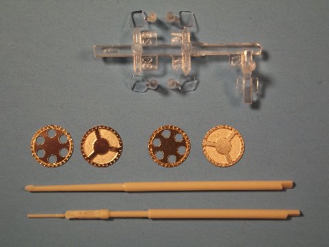
Photoetched grates, clear ‘lights’ and periscope detail parts
Over the course of a three-month evaluation process we went through two test shot cycles. The work above is from the second test shot I got for examination. By this time, as two examples, we had refined the look of the two styrene optical periscopes and form of the photoetched (PE) main sea water suction and discharge gratings.
We all have Bill Rogers to thank for unearthing that photo of the MSW gratings. Nowhere else have I found a definitive look at those main condenser openings, unique to boats employing the S5W nuclear plant. Though the dry-dock picture is of a Polaris boat, it (as so many other American, and even one British, early nuclear powered submarines), like the SKIPJACK’s, made use of the same S5W plant. So, it’s a logical expectation that the MSW gratings seen on this Boomer were very similar to those on the SKIPJACK boats. Anyone out there who can make a liar out of me? Let’s see what you got!
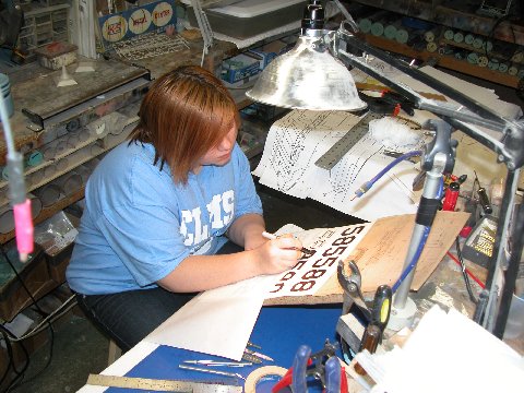
Apprentice hard at work on ‘inport’ sail numbers – ‘old school’
There’s something to be said for slave-labor! I’ve found that staff productivity is directly proportional to the voltage applied. As the SKIPJACK work turned into a grind I noted that my Granddaughter had been getting into manga sketching big-time and was showing some talent. So, never one to waste an asset, I dragooned her into the shop to help me with the decal and PE graphics. She told me that she could punch it all out on a computer. Hell, no, I said. Regardless, she snuck out when I was involved in something else, got to the computer and took it as far as finding the correct fonts somewhere in digital-land. I put a screeching halt to that! Here, recaptured, Rose – an ankle chained to a leg of the desk – is inking the decal artwork.’ What’s with the attitude, Rose!? … give us a smile!”
As with PE artwork, its good practice to render the decal artwork several times the eventual size of the finished product (PE or decal contact negative/positive). As the artwork images are reduced in the process camera – or, these days, scanner – image density increases and becomes ‘tighter’. Rose is working to a five-to-one ratio, if I remember correctly.
Trackbacks:
2 Responses to Moebius 1:72 Scale SSN Skipjack: Development and R/C Conversion – Part 3