
Report to the Cabal: Part 9
SAS Theory and Preparing to Outfit the Sub-Driver
R/C submarining – above all other forms of R/C vehicle assembly, set-up, operation, and maintenance – is the most demanding. It’s an activity that requires investment of serious money, time, tools, and talent. And R/C model submarining is made an even more difficult to achieve pastime owing to the limited availability of clean, easily accessible bodies of fresh, untreated water. It is much to overcome if you are to enjoy this hobby.
The Sub-Driver (SD) is a complicated system that is much easier to comprehend if you study the mechanisms and devices which make up the three major SD subsystems: Propulsion, Control, and Ballast. Endeavor to understand the HOW and WHY of each subsystem’s function and you will come to know how the overall system achieves the tasks of keeping things dry, moving the submarine along, control, and how its weight is changed to float the boat or get it to submerge under the water.
First, a little ‘Semi-ASpirated’ (SAS) ballast subsystem theory, operation and device description. Then, onto the nuts-and-bolts of turning devices (electrical and electronic items) and mechanisms (mechanical and plumbing items) of the coherent system.
SAS THEORY
The SAS ballast subsystem works to manage ballast water by opening a servo-actuated valve atop the ballast tank to vent air out so water (the ballast) can flood in through openings in the bottom of the tank (this is identical in form and function to the “gas and snort” ballast subsystems of the past.) However, the SAS differs from previous ballast subsystems in that it empties the ballast tank by discharging air – either from atmosphere (through the snorkel head-valve), or scavenged (from within SD dry spaces) into the ballast tank, forcing the ballast water out. With the exception of the snorkel assembly and the safety float-valve, the SAS plumbing (brass nipples, internal & external hoses and external manifold) is arranged very much like the old snort ballast sub-system. The unique feature of SAS is its ability to empty a significant fraction of the ballast tank while operating submerged (to a depth no deeper than fifteen feet) without need of a dedicated liquefied gas source or space-consuming bladder(s).
SAS OPERATION
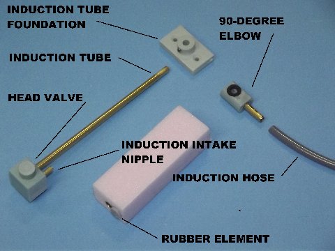
SAS components identification
Atop the snorkel assembly mounted within the sail, a rubber disc, pushed up by a float (pink ‘block’), blocks the head-valve inlet when water fills the sail cavity. With no water buoying the float upwards (the model completely in surface trim or the sail broached), air is taken from atmosphere to empty the ballast tank: Air passes down through the snorkel assembly’s induction tube to a cast resin, 90-degree elbow fitting within the hull (equipped with an O-ring to insure a gas-tight seal between the lower portion of the tube and elbow) to a length of flexible hose. This runs to a manifold atop the SD, where another length of flexible hose runs aft to a brass tube nipple at the motor bulkhead, then through an internal length of flexible hose into the suction side of the low pressure blower (LPB) or (via a T fitting in the flexible hose within the SD) to the SD dry spaces through the safety float-valve. All plumbing items between the snorkel head valve and LPB inlet are elements of the induction line.
The LPB compresses the air and sends it, through a short length of flexible hose within the SD, to a nipple on the motor-bulkhead, where another external length of flexible hose makes up to a nipple on the manifold, and from there the compressed air is discharged into the top of the ballast tank, pushing the ballast water out. All plumbing items between the manifold and LPB outlet are elements of the discharge line.
Normally, the safety float valve permits air to enter or leave the SD’s dry space through the open snorkel, or pass air from within the SD to the LPB when that device is running and the snorkel head valve is shut. The safety float valve is a back-up: Should the snorkel head valve fail, or a leak occur anywhere along the induction line, the safety float valve will close, blocking water in the flooded induction line from getting into the SD dry spaces.
THE R/C SYSTEM
The R/C system, in the face of industry change to systems working in the 2.4gHz band, is worthy of discussion. Radio waves in the 27, 40, 72, 75mHz and near-by bands have no problem punching through fresh water. However, hobby R/C transmitter manufacturers today have transitioned almost exclusively to systems that operate way up there on the 2.4gHz band. Unfortunately (and why micro-wave ovens blast food at this frequency) 2.4gHz is the full-tone resonate frequency of water molecules. In short, the newer R/C systems send & receive a signal modulated to a carrier wave that won’t penetrate water!
Hence, the 2.4gHz R/C systems are totally useless for vehicles operating underwater. Fortunately, as most R/C system manufacturers were converting exclusively to 2.4gHz, Caswell Inc. entered into an agreement with the WFly company to continue production of R/C transmitters on the traditional lower-band frequencies. Today, with the departure of Polk’s from the R/C system scene, Caswell, along with Futaba (with their F-14 & F-16 series of marine friendly R/C systems) are just about your only source for R/C transmitters and receivers that can send a signal through water.
Now, a look at the many electrical and electronic devices that fit into the SD, what they do and how they interrelate:
- WFLY-8 TRANSMITTER: A fast, highly maneuverable submarine like the SKIPJACK demands use of a ‘computer’ type transmitter, one with the ability to set the end-points (maximum deflection of control surfaces and top/low-end of throttle commands), permit stick mixing to coordinate turning-diving maneuvers, servo reversing, stick and switch re-assignment and hold changes in memory, all for a specific model – things the old-style, basic four or six-channel R/C transmitter can’t do. The WFly-8 transmitter does just that and is what you need. Plus it has a removable RF module which can be swapped out for an RF module of the synthetic crystal type, which permits quick, assured frequency changes in the field.
- SL-8 RECEIVER: Caswell-Merriman advocates the purchase and use of either the Sombra Labs crystal controlled Lepton-6, or synthetic crystal (programmable to any channel on the 72-75mH bands) receivers because of the magnificent selectivity (the ability to ignore all interfering electrical noise) of these receivers in the tight confines of a SD. The inverse square law applies to signal/noise strength between the receiver and signal/noise sources; the closer the receiver to the noise sources, the more overpowering the noise over the signal being detected. Only the Sombra Labs receivers have proven to be nearly noise-proof in these applications. Because of their selectivity, and other features, the Sombra Labs receivers are recommended for the entire line of Caswell-Merriman SD’s.
- MPC-LPB (provided): The air pump used to push air into the ballast tank is, in this application, called a low pressure blower (LPB) and attached to the motor can of the LPB is an electronic switch, or motor pump-controller (MPC). The device comes installed and tested with the SD. The power leads from the MPC are wired to the battery power cable and the lead plugs into one of the two outlet ports of the Y lead that originates from the Automatic Depth Finder (ADF) fail-safe circuit.
- VENT SERVO (provided): This micro-size servo set into the dry side of the after ballast bulkhead operates the linkage within the ballast tank that opens and closes the ballast tank vent-valve. The servo plugs into the second output leg of the Y lead coming from the ADF’s fail-safe circuit.
- Automatic Depth Finder (ADF): Designed and produced by Kevin McLeod, the ADF is a combination of two circuits vital to the operation of an R/C model submarine. One circuit is an angle-keeper that plugs in between the receiver and stern plane servo – it senses angular displacement about the pitch axis and sends corrective signals to the stern plane servo. The other circuit, a ‘fail-safe’ which generates a ‘blow’ command to the vent valve servo and motor pump controller of the LPB should either battery voltage drop to a critical value (what the Lipo-Guard does) or should the transmitted signal be lost – either situation results in positioning of the vent valve to shut, and the LPB on to pump air into the ballast tank, surfacing the boat. The angle-keeper circuit input comes from the receivers channel-6 port. The fail-safe circuit input comes from the output side of the Lipo-Guard.
- LIPO-GUARD: When using the lithium-polymer battery, provision has to be made to detect the low voltage point below which permanent battery damage occurs. The Lipo-Guard not only detects that critical voltage, but works to interrupt the signal to the fail-safe when that happens, causing the fail-safe circuit to command the ballast-sub system to cycle to the ‘blow’ condition, surfacing the boat. And the Lipo-Guard will not permit a “reset” of the fail-safe until the battery voltage is raised above the critical voltage – the consequence of a battery change. The input side of the Lipo-Guard plugs into the channel-4 port of the receiver. The Lipo-Guard’s two voltage sensing wires hook up directly to the battery power cables.
- HIGH CAPACITY BEC: A dedicated voltage-regulator to drop the battery voltage to the 5-volts needed by the devices that feed off the receiver bus is needed due to the high bus load from so many devices. The recommended high capacity battery elimination circuit (BEC) produces up to 5-Amps of current to power the SD’s devices – much more than a typical ESC’s (electronic speed controller) BEC. The high capacity BEC outputs into any unused channel port of the receiver.
- STERN PLANE SERVO: One of the three mini sized servos screwed onto the resin servo rails. Through its push-rod, this servo operates the model’s stern planes. The lead from this servo plugs into the output side of the ADF’s angle-keeper circuit.
- RUDDER SERVO: This mini servo operates the rudder linkage. This servo’s lead plugs directly into the channel-1 receiver port.
- SAIL PLANE SERVO: This mini servo operates the sail plane linkage. It plugs into the channel-2 port of the receiver.
- ESC: The recommended electronic speed controller (ESC) is the MTroniks Marine-15. This programmable speed controller is compact, reliable and completely waterproof. It’s input power wires make up directly to the power cables, and the lead plugs directly into the channel-3 port of the receiver (after disconnecting the leads red wire from the plug – more on that later).
And now the non-electrical mechanisms associated with the SAS ballast sub-system (these items come installed and pre-tested):
- SNORKEL ASSEMBLY: This item comes with the 3.5 SKIPJACK SD and is detailed later on. A key element to the SAS ballast sub-system in that it works to block off water from getting into the induction line once the sail dunks underwater, and opens again when the sail broaches the surface. When the snorkel head-valve shuts, the LPB is forced to draw air from within the SD’s interior.
- SAFETY FLOAT VALVE: This float-operated valve steps in to isolate the SD’s interior from flooding should water get into the induction line.
- FOUR-POINT MANIFOLD: A cast resin manifold where the snorkel, and some of the discharge and induction flexible hose elements gather at a centralized point atop the SD cylinder. The manifold is where LPB discharge air enters the ballast tank.
- VENT VALVE: This servo-actuated valve dumps the air within the ballast tank when the command is given to flood. At all other times the vent valve is in the closed position.
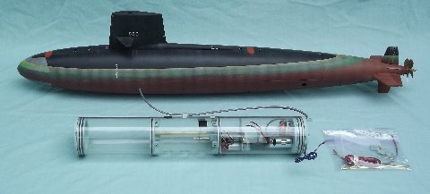
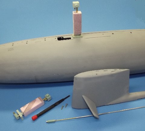
Relative size of the Sub-Driver (SD) to a 1/72 scale SKIPJACK
Right is pictured a stock 3.5 SKIPJACK Sub-driver, next to a Scale Shipyard 1/72 SKIPJACK – a model I’ve been operating for over ten years and used as a ‘test-mule’ to evaluate SD systems. The SD arrives to the customer with all propulsion and SAS sub-system hardware installed and tested. Its up to the customer to purchase, install and set-up the needed devices to get it operational.
The SKIPJACK SD is a 21″ long, 3.5″ diameter, 1/8″ thick clear Lexan cylinder divided into three spaces by two internal ballast bulkheads and a removable bulkhead at either end. The ballast tank is sized to get the submerged model to the surface and to float there at the SKIPJACK’s design water line.
The SD comes with the snorkel assembly and all plumbing required to interface the SD’s SAS sub-system with the model proper. It arrives with an installed and tested LPB with attached motor pump controller (MPC); installed 555 size 12-volt motor geared 3:1; and installed ballast subsystem servo and linkage.
I’ve omitted the servo actuated ballast tank vent valve for clarity. This is the arrangement of the SAS components and plumbing, within and outside the SD.
- Snorkel Assembly – a float operated head-valve works to isolate the induction line from atmosphere when the sail of the model submarine submerges. The snorkel portion of the induction line connects with the safety float-valve portion, both of which can dump air – from the surface or from the SD – into the low pressure blowers.
- Safety Float-Valve – a float operated valve which works to isolate the SD’s interior from a flooded induction line.
- Low Pressure Blower (LPB) – a diaphragm, positive displacement type pump that normally compresses air, but will move water without damage. It is the same unit used in our snort configured 3.5 SD’s. The LPB’s job is to send air, regardless of source, into the ballast tank.
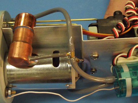 Here’s the practical installation aboard a 3.5 SKIPJACK SD. We’re looking at the underside of the aluminum motor bulkhead device tray. The cast resin motor bulkhead to which all devices are attached – with the exception of the ballast subsystem servo – is to the extreme left. The suction side of the blue LPB pump connects, through flexible hoses, to the induction side of the SAS plumbing. The LPB can either take air from within the SD through the safety float-valve (that copper thing near the motor-bulkhead) or air from atmosphere through the snorkel head-valve up in the model submarine’s sail. The discharge side of the pump leads to the ballast tank.
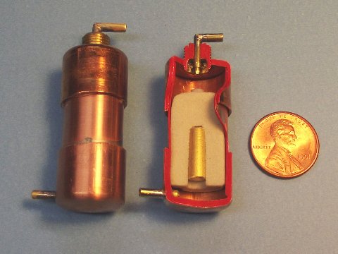
Safety Float Valve and cutaway showing internal construction
The safety float valve, as long as no water gets into it, permits air from the induction line to either enter or be pulled from the dry spaces within the SD. Atop the float a rubber element blocks the inlet/outlet nipple should water get into the valve body. It’s the job of the safety float valve to isolate the interior of the SD from the induction line should the induction line flood.
The snorkel assembly (provided with the 3.5 SKIPJACK SD) fits atop the SKIPJACK’s hull and under the removable sail structure.
Snorkel assembly mounted inside the sail
This mechanism permits surface air to be pumped through the LPB into the ballast tank, blowing it dry. However, should the snorkel head valve be shut (when underwater), the LPB will scavenge enough air from within the SD to displace a significant fraction of the ballast water before pump back-pressure (dropped pressure within the SD dry space) is enough to distort the pump’s flexible bellows to the point where they no longer can push air.
The snorkel assembly mounted atop the hull is protected by the free flooding, removable sail structure. It is vital that the float be unobstructed, free to rise and fall along the brass induction tube. When buoyed up, the rubber element atop the float blocks the inlet nipple of the head valve. All unions – from the head valve down to the motor bulkhead nipple – have to be tight or they become water entry points, resulting in flooding of the induction line. If the SAS subsystem can be said to have an Achilles heel, it is failure points somewhere along the induction line external to the SD’s interior.
This is what makes the hobby of R/C model submarines so damned expensive: the Sub-Driver itself with all the devices needed to power, control and change the weight of the boat. Not just the typical R/C devices like servos, receiver, battery, ESC and the like, but highly specialized devices: the Lipo-Guard, MPC, ADF and SL-8 receiver.
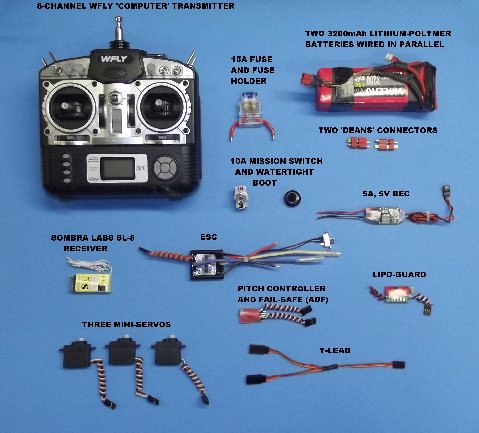
Shopping list illustration
These are very specialized items, produced in limited quantity and hence expensive to produce and market. We pay a premium for the ability to operate our craft beneath the waters surface.
To the right are most of the devices you’ll need, all of them available from Caswell Inc. (http://www.sub-driver.com/)
Complete shopping list (in addition to the SKIPJACK model kit, SD & the Fittings Kit):
- 32000, 11.1-volt Lithium-polymer battery. Two of these are required, wired in parallel they provide enough capacity to run your 1/72 SKIPJACK all afternoon long.
- Two sets of the Dean’s connectors to make up the battery to your power cables, and to make up the motor-bulkhead devices to the other end of the power cable.
- 10-ampere, DTSP toggle-switch and watertight boot
- Optional 15A quick-blow fuse and fuse holder
- Five volt, 5-ampere battery eliminator circuit (BEC)
- Sombra Labs SL-8 synthetic crystal receiver
- MTronik’s Marine-15 ESC
- ADF, combined angle-keeper and fail-safe circuits
- Lipo-Guard, to protect the Lithium-polymer battery against low voltage
- Three mini-sized servos
- Y type servo lead, to split and send the signal from the channel-4 receiver output to the LPB’s motor pump controller (MPC) and ballast sub-system vent servo.

Battery connected devices
Four of the devices within the SD require hook-up to the battery directly, all wired in parallel to a common Dean’s type plug that will mate with the plug made up to the power cables. The four devices take battery power for the following services:
- ESC: Send power directly to the propulsion motor after conversion to the correct polarity and amplitude
- Lipo-Guard: Sense battery voltage to protect the lithium-polymer battery
- MPC: To power the LPB’s motor
- BEC: To produce a regulated 5-volts required by the receiver bus
With the exception of the BEC, the devices connect directly, or through one or more devices, to the receiver from which the ‘intelligence’ you provide at the transmitter is conveyed.
On the left side of the devices pictured above is the power cable which originates in the forward dry space where its Dean’s plug makes up to the battery, through a series wired mission-switch, to an optional fuse, where the cable then runs through the brass tube conduit through the ballast tank, into the forward dry space where another Dean’s plug makes up and delivers battery power to the four devices, all wired in parallel with their common plug.
The toggle of the mission-switch projects to the wet-side of the forward bulkhead and is made watertight with a flexible rubber boot.
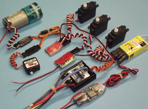
Illustration of the R/C subsystem’s device connections
This is how all the devices that mount onto the motor bulkhead are hooked up to the receiver, either directly or through other devices. The rudder (channel-1), sail plane (channel-2) and ESC (channel-3) plug directly into their respective receiver ports. The BEC also plugs into an unused receiver port, but only to apply power to the receiver bus, which powers the other devices. The receiver channel-6 port accepts the lead from the angle-keeper side of the ADF, and from the ADF to the stern plane servo, the upper-most servo pictured.
The receivers channel-4 port is for control of the SAS devices, and deserves a bit more discussion. The Lipo-Guard, which plugs directly into this port, is directly connected to the battery cable, through which it monitors the battery voltage. The Lipo-Guard will drop the transmitted channel-4 signal – simulating a ‘loss of signal’ condition – should battery voltage drop to the critical level. This triggers the ADF’s fail-safe circuit, which is next in line, to generate the pulse-length required to start the ballast subsystem into the ‘blow’ condition and surfacing the boat. So, the devices connected to the receiver channel-4 port go like this from the receiver: Lipo-Guard; fail-safe side of the ADF device; a Y lead to split the signal and send it along to the MPC of the LPB, and the ballast subsystem servo. (Near the top of the above photo you see the Y lead feeding the ballast subsystem servo and MPC.)
Four devices have to be hard-wired into the battery cable: the MPC (power to the LPB pump as directed by the MPC); Lipo-Guard (voltage sensing); ESC (chopped current of appropriate polarity and amplitude sent to the propulsion motor); BEC (regulated voltage of a relatively high current rating to the receiver bus where the other devices draw their power).
Most, but not all devices have two sides to them: the receiver side, and the battery side. Observe correct polarity when you hook things up, or the magic smoke will be loosed.
Today’s ESC’s usually contain a low current BEC within them, but only rated for a maximum continuous current draw of 1.5 Amps. That’s fine for what a reversible ESC’s BEC is tasked to do for most model cars and boats: provide 5-volt power to just the receiver and one or maybe two servos. But, in an R/C submarine, where as many as TEN devices are sucking off the receiver bus … well, that’s way too much of a load for the ESC’s BEC. In a model submarine, even in the idling condition, the current passing through the receivers PC’s foil is over 2-Amps! When the servos are at work and pushing against a load (those watertight seals!), the total current draw of the system can spike system current draw to nearly 5-Amps! Hence the need for a dedicated, high current BEC.
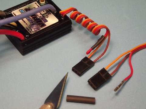
Disabling the ESC’s internal BEC & making ‘safe’ the pulled wire
However, using a separate, dedicated BEC requires disabling the ESC’s BEC to prevent interaction between the two and sending transients along the receiver bus, potentially glitching the system. Disable the ESC’s BEC by pulling the red-wire pin out of the J-connect at the end of the ESC’s servo lead. Fold the metal pin back on the red wire, slip on a length of heat-shrink tube, and shrink it down with a hot-air gun this to insure you don’t short the bare ‘hot’ pin against a ground in the SD.
Trackbacks: