
Report to the Cabal: Part 8
Securing the Internal Hardware and Structures
If I gave the impression in a previous installment of this article that the lower bow piece could be installed to the upper hull half before installation of the torpedo tube nest assembly (the three piece structure comprising nest transverse bulkhead-F, nest keel piece-G and torpedo muzzle bulkhead-I), I was mistaken. The nest assembly must first be assembled, CA’ed within the forward hull piece and only then can the forward hull piece be glued to the upper hull half. I want to get the chronology straight before someone paints themselves into a corner.
At this point most of the major assembly chores have been done. All that is left is to: 1) screw the three pieces of the torpedo nest assembly together and glue it into the lower hull section (the one sawed off from the lower hull), 2) mount that bow piece under the forward end of the upper hull, 3) make up the securing screws to the sub driver (SD) shock-absorber and strap foundation and finally 4) test fit the SAS snorkel assembly (if used).
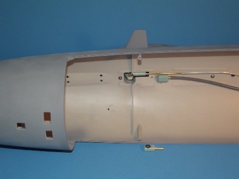
Affixed upper hull attachments, including sail anchor screws
Note here the two round-head 4-40 machine screws that run up from inside the upper hull, through the base of the sail and into the thread of the sail foundations. This is how the sail is pulled down securely upon the hull.
I’ve made up the sail plane push-rod to demonstrate how its magnet engages the magnet partially encapsulated within the resin arm of the lower sail plane bellcrank. The short length of tube extending into the hull projects into and is made tight by the elbow’s O-ring. The elbow unit in foreground shows off this sealing O-ring.
The 90-degree elbow fitting that mates up to the induction tube permits the rather stiff ‘flexible’ induction hose to make up to the manifold atop the SD without getting in the way of the sail plane pushrod. The elbow accepts, through its watertight O-ring, the projecting induction tube, the body of the elbow rests up against the top of the hull where it is slathered with RTV adhesive to hold it in place, as you see in the elbow glued within the top of the upper hull. This permits removal of the entire snorkel assembly for maintenance, yet assures watertight integrity of the snorkel assembly when reinstalled.
The reason for making the sail removable is to afford access to the hull mounted semi-aspirated (SAS) Sub-driver ballast sub-system snorkel assembly, as well as to adjust the sail planes if needed. The snorkel assembly comes with the Sub-driver (SD).
The reason I had you assemble the two sail halves together, but not the top of the sail, was to permit viewing through the open top of the sail as you check the snorkel float free to run the 1/4″ or so vertically without rubbing up against the inside walls of the sail. Once satisfied that all is well within, the sail is taken off the hull and the top piece glued in place with thin formula solvent cement.
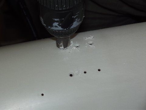
Beveling the SD shock absorber mounting screw holes for a flush fit
Before running through the screw fasteners through the bottom of the hull – to make fast the SD shock-absorber and strap foundation – I beveled the outside of the holes to counter-sink the flat-head screws. Use a variable speed drill here and keeping the speed slow insured the plastic did not melt and make a mess of things. The only special consideration when working polystyrene with power tools is to use a sharp bit, keep the speed low and go real easy on the feed rate.

Sub-driver shock absorber (center) mounted in lower hull
The job of the SD shock-absorber is to dissipate collision energy through physical displacement of the SD within the hull. So doing, the shock-absorber enhances the models ability to avoid handling and running damage, damage that often manifests as shearing of the SD indexing pin or crushing of the models bow when you experience the inevitable ‘hard knock’ against pool side or collision with an advisory. The SKIPJACK is a fast boat and there will be occasions when you’re driving so fast that the boat gets ahead of your reflexes or ability to back-down in time to prevent a ‘bump’.
The shock-absorber works like this: If a knock is of sufficient force to move the SD longitudinally within the hull, a spring within the shock-absorber is compressed, as the mass of the SD sends it sliding forward within the hull. The spring quickly returns the SD back into position – the event may cause the the drive-shaft and control surface magnetic links to part, but you will have avoided significant damage to the models hull, indexing pin, or SD. A shock-absorber is recommended for all models employing 3.5 sized SD’s and up.
Once I ran the securing screws through the hull and foundation of the SD shock-absorber I ran down the 2-56 nuts and tightened them. A drop of CA over each nut keeps them from vibrating loose. CA was then smeared around the base of the shock-absorber where it meets the hull.
The torpedo nest assemblies primary job is to stiffen the bow of the SKIPJACK against handling and collision damage.
Keep in mind that the Moebius Models 1/72 SKIPJACK model kit is principally made of so-called ‘high-impact’ polystyrene. A plastic that has nowhere the strength and shock resistance of glass reinforced plastic (GRP), today’s preferred substrate for model ships and submarines. Hence the inclusion of the torpedo nest assembly, which, only incidentally serves as a foundation for practical torpedo tubes.
The only ‘optional’ item supplied in the fittings kit is the torpedo tube nest foundation (torpedo tube foundation-H) – most of you will toss that part into the trash, but it’s included in the kit for you meat-eaters. (Sorry, Norbert … I read your book, you magnificent so-and-so!).
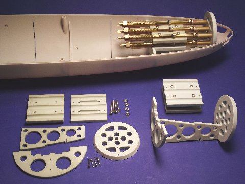
Torpedo nest & nest foundation components with example of installed weapon pack.
In the picture (right), a nest of six 1/72 torpedo tubes, secured within the nest foundation, all sit secure and in proper registration atop the keel piece. The muzzle ends of the tubes project into and are held in alignment by the torpedo muzzle bulkhead. I realize most of you will not opt for the weapons system, this is just some eye-candy for you; a suggestion of what can be done with R/C model submarines today.
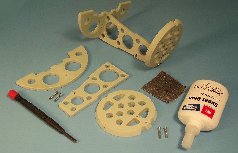
Nest foundation assembly: components, installation tools & assembled example
Within the lower hull will be mounted this three-piece nest assembly. It’s primary job is to stiffen the forward hull against impact and torsional forces. The secondary function of the nest assembly is to serve as a foundation for the removable torpedo tube nest, should you elect to make the SKIPJACK model a torpedo shooter.
With a hard sanding block, sand the nest assembly contact surfaces with #240 to provide some tooth, then attach the three pieces together with the provided screws.
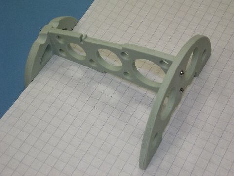
Checking nest foundation assembly alignment using graph paper
The three pieces that make up the nest assembly attach together with the aid of four 2-56 round-head machine screws. A quick and easy means to insure that the torpedo muzzle bulkhead and nest transverse bulkhead fit perpendicular to the nest keel piece is to lay the assembly over some graph-paper and eye-ball it. Block sand the forward or after keel edge to eliminate any cant that produces a fit that is not perpendicular. Once you have the three pieces of the nest assembly straight, hit their joints with thin formula CA adhesive and spritz on some accelerator.
Note how the bottom edge of the longitudinally running keel piece indexes with the anchor well and frame that projects up from the bottom of the forward hull piece – it insures that you get the nest assembly to sit the correct distance from the front of the boat. The only thing you can screw up is the nest assemblies radial orientation within the hull and two engraved lines, one either side of muzzle bulkhead will help you to get that right as well.
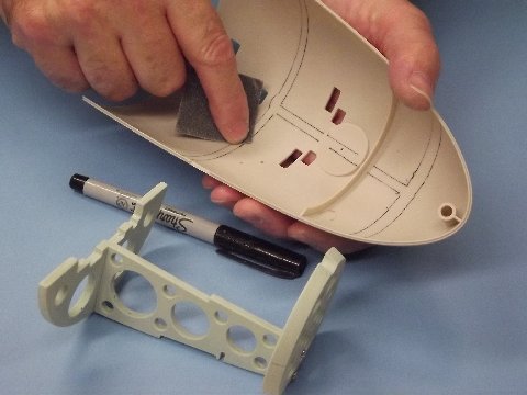
Roughing the mating surface area with sandpaper for better CA adhesion
As you test fit the nest assembly into the lower bow piece you mark off the contact points between within the hull with a pencil or pen. Remove the nest
assembly and rough up the contact areas with #240 sandpaper. Don’t forget to do the same for the upper hull half, where the torpedo muzzle bulkhead will make contact in that section.
If you are going to equip your SKIPJACK with a practical weapon system, now is the time – before installing the nest assembly – to grind and file open the torpedo shutter doors.
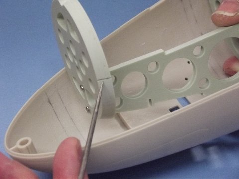
Engraved indexing mark aids proper radial orientation of assembly
Molded into the sides of the torpedo muzzle bulkhead are engraved longitudinal lines to guide you as you register the nest assembly to the lower hull piece. When lining up the assembly you rotated it until the two engraved lines fall along the edge within the bow piece – the attached keel and bulkheads follow as proper radial alignment is achieved. Pressing the assembly down tight into the lower hull, tack-glue it to the hull with staggered dabs of thin formula CA. Release the pressure, then check again for proper alignment and once happy with things, lay on thick formula CA along all contact points and let it soak in and harden. Don’t spritz the still wet adhesive with accelerator – you want complete penetration of the adhesive, to get it between all resin and styrene surfaces. Leave the CA to cure naturally.
If you wish to equip your 1/72 SKIPJACK with teeth, I recommend the Caswell-Meriman weapon system. Each weapon system package contains one launcher (which can be configured for either mechanical or pneumatic actuation) and three gas propelled torpedoes/weapons. (http://www.sub-driver.com/torpedo-systems.html)
The fittings kit supplied torpedo foundation (torpedo tube foundation-H) is optional and is only used if you opt to include the ability to launch weapons. The nest foundation assembly – in addition to its primary job of stiffening the bow – is designed to accept and hold in perfect registrations the removable torpedo tube nest.
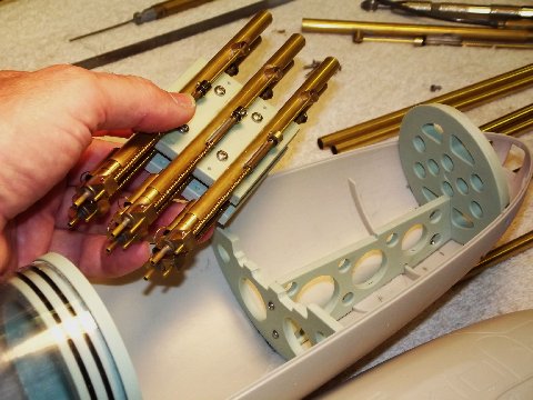
View of assembled torpedo ‘nest’ and installed foundation assembly
This picture shows to good advantage how the lower edge of the keel piece indexes the nest assembly longitudinally by engaging the forward frame and raised anchor well. Note that in this shot, the bow portion of the lower hull half has not yet been razor sawed away.
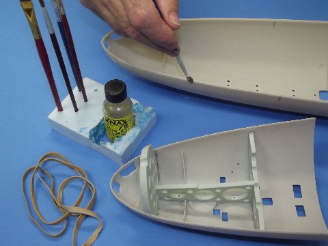
Gluing the lower hull ‘nose’ onto the upper hull piece with the foundation assembly in place
Time to glue the forward lower bow piece to the upper hull half. Note the pencil mark near the inboard and outboard edge of the upper hull – marked off to indicate where to stop brushing on the thin solvent cement used to soften up both the upper hull matting edge and lower bow section mating edge. Once you get the mating edges gooey (it’s a proper word … look it up, dammit!) the two pieces are assembled, more thin solvent cement was run into the seam where capillary action pulled it into the gap and the two pieces start to fuse together. To insure a tight seal, rubber-bands are wrapped around the assembly.
 The inset flat heads of the shock-absorber and strap foundation screws on the bottom of the hull need to be secured permanently and faired to conform with the hull. A drop of thin CA adhesive is dabbed onto each screw head and left to soak in about a minute, followed by a sprinkling of baking soda which wicks up the adhesive and immediately cures to a solid – an instant, hard filler ready for filing. The CA-baking soda filler is worked with file to conform to the curvature of the hull.
Note the CA work-station-caddy I’ve cut from a hunk of foam sheet – keeps all CA adhesives, accelerator, glue mixing cups and open tray of backing soda handy for quick and easy use. When a CA gluing job calls for a mixture not too thin, but not too thick, I’ll mix a bit of thick and thin CA into a cup and use a stick or rod (such as above) to transfer the adhesive to the work.
Trackbacks: