
Report to the Cabal: Part 4
[This one’s dedicated to my East Coast model submarine buddies, like Ray Mason who are sitting in the dark, waiting for the lights to come back on and the water to depart. Hang in there, guys!]Parts One through Four serve as preamble to the meat of this series, a detailed discussion – an instruction manual, if you will – on how to employ the Caswell-Merriman ‘Moebius 1:72 SKIPJACK Fittings Kit’ to convert the static display plastic model kit to a practical, well running and robust R/C model submarine.
I had little input as to how the kit was engineered. The only input I had was to ask that there be a longitudinally running, horizontal break between the hull pieces, be they two long ones, or the top and bottom halves divided into quarters. This to achieve a removable upper hull half to afford internal access for R/C versions of the model. I also asked that the hull pieces be of substantial thickness (3/32″ the ideal); that the lower and upper hull halves (or quarters) be outfitted with internal stiffening frames; and that there be provided a tight fitting system of pins and tongue-in-groove hull edges that would insure positive registration of the two removable hull halves. Other than that, the guys at the point of manufacture did all the engineering – and what a wonderful job they did, resulting in a sturdy, well fitting, easy-to-assemble plastic model kit with a minimum of parts.
The mock-up SKIPJACK kit – though fabricated in a 3D machine – was broken down into parts and the parts indexed as the eventual kit would be. Inspection of the mock-up kit revealed that my wants had been incorporated. I was delighted as in this game you have to be ever mindful that the product is primarily targeted at the vast majority who will only assemble the kit for static display. Fortunately the things I asked for did not impact on the cost of the kit, so they were incorporated.
So, with my work for Moebius completed, I directed my considerable talents and good looks to the service of the Caswell empire – the design, fabrication, and packaging of R/C conversion kits needed by our customers who wish to turn the Moebius SKIPJACK into a well-running R/C model submarine. Before the kits hit the West Coast, I had completed all the fittings kit masters and tools, and was well underway with part production. I could do that as I made use of the second generation test-shot kit parts to give form to the masters that were conformal to the inside surfaces of kit parts. Masters were built up from test-shot kit parts (all the control surfaces) automotive filler, brass, plastic sheet, RenShape, foam-core PVC sheet, and white-metal castings.
Parts Legend
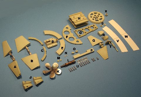
Below is a visual presentation of the items that make up the Moebius 1:72 SKIPJACK fittings kit, along with a table below denoting the name and function of each item:
A stern planes and yoke
B rudders and yoke
C after Sub-driver foundations
D Sub-driver shock absorber
E forward Sub-driver foundations
F nest transverse bulkhead
G nest keel piece
H torpedo tube nest foundations
I torpedo muzzle bulkhead
J propeller shaft foundation
K propeller
L propeller shaft, bearings and coupler
M hull rudder hole blanking discs
N sail plane operating shaft bushings
O hull stand hole blanking pieces
P Sub-driver restraining strap foundation
Q sail planes and bell-crank
R sail-to-hull mounting foundations
S sail plane bell-crank shaft retainers
T sail plane bell-crank
U mechanical fasteners
V after radial flange
W forward radial flange
X upper hull securing screw and foundations
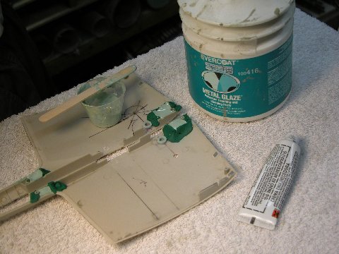
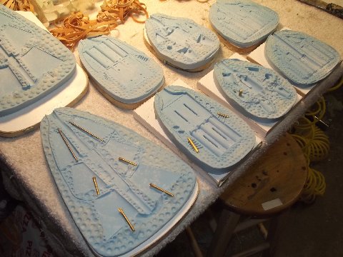
The first area I addressed as I went about the chore of creating masters was the stern. Specifically, the two-piece foundation needed to mount the propeller shaft bearings. I started by removing the strengthening rib and single longitudinal brace in the area of the two stern hull quarters. I CA’ed a half-circle sheet-plastic transverse dam forward and a blanking sheet butted against the after end of the hull, where the base of the propeller hub would fit. These dams are to contain the thinned down filler used to give form to the foundation masters.
I waxed the inside of the containment to prevent the hardened filler from sticking to the styrene.
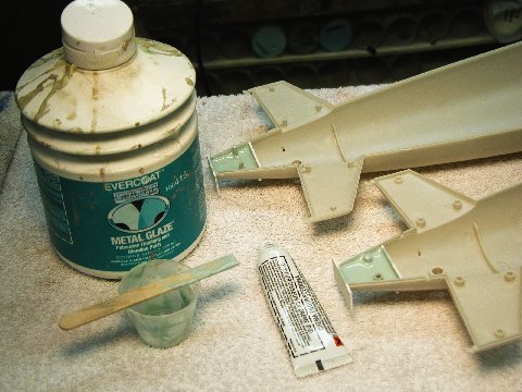
Pouring the filler into the stern
I thinned the filler with lacquer thinner till the mix was runny enough to insure a bubble-free fill of the stern areas with the gooey stuff. I mixed in a little hardener, poured and pushed the stuff into the stern areas and waited for the filler to cure.
Automotive filler will shrink a bit if used straight out of the can. Even more when you cut it with thinner. So, I was compelled – after the two halves of the propeller shaft foundation master cured – to pull them out, re-wax the interior of the hulls, smear uncut catalyzed filler on the contact face of the masters, and smashed them into place, where they remained till the filler had hardened. The glaze I put on the parts made up for the shrinkage and produced a tight glove fit to their respective spots on the hull stern pieces.
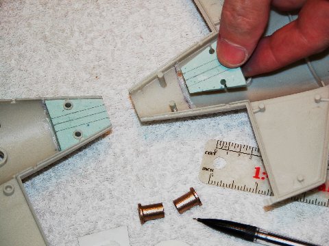
Preparing to fit the propeller shaft foundation parts for the Oilite bearings
The two halves of the filler formed propeller shaft foundations were marked out. Filed out those channels would form the bore hole through which the two propeller shaft Oilite bearings would fit. Extreme care was taken to insure that the center-line of the two channels ran perfectly in alignment with the hulls longitudinal axis.
To make the reach of the long push-rod between the after end of the Sub-Driver (SD) – the watertight cylinder containing the propulsion, ballast, and control sub-systems – motor-bulkhead a simple one, I employed a partial bevel-gear linkage within the sail to translate the axial motion of the push-rod (mounted up against the inside of the upper hull) to the rotary motion, up within the sail, needed to activate the sail plane operating shaft.
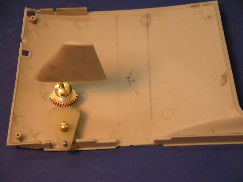
Sail plane activation bevel gear mounting
The masters of the two partial gear elements are seen here. A small cylindrical magnet within the eventual cast resin lower gear element engages a magnet at the forward end of the sail plane push-rod. A similar magnetic coupling at the after end of the push-rod produces a near slop-free linkage between servo and sail planes.
These masters, along with the others, would be degreased, cleaned up, (pickled, if metal), primed then used to make rubber production tools.
I needed solid foundations within the forward and after bottom ends of the sail through which securing machine screws would hold the sail down upon the hull – permitting removal of the sail from the hull for sail plane linkage and snorkel induction head valve and float adjustment or maintenance.
Pouring sail mounting blocks
The masters of those foundations formed – like the propeller shaft foundation masters – from thinned down two-part automotive filler poured into the area of the model part where the eventual model part would fit. Here I’ve formed the containment dams from oil-based modeling clay. However, with these, the last step was to assemble the two sail halves and hold them tight with masking tape as the last application of filler, applied to the outboard faces of the foundation masters, acted as an adhesive to form two solid foundation masters.
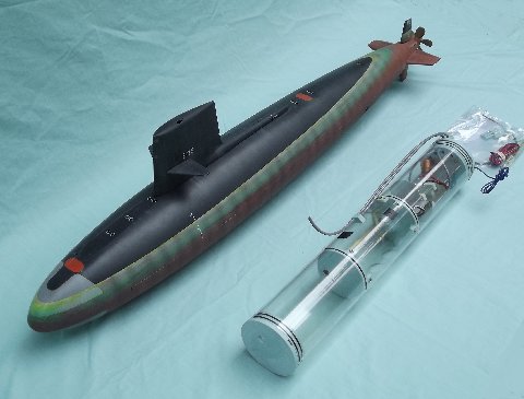
Scale Shipyard SKIPJACK and Sub-Driver ‘proof of concept’
As I worked up the masters for the Moebius Models 1:72 SKIPJACK fittings kit, I developed the jigs, templates and plumbing masters needed for production of a dedicated 3.5″ diameter, SAS type, single-motor SD to handle the ballast, control, and propulsion of this kit. I used my old, faithful Scale Shipyard 1:72 SKIPJACK model as the evaluation hull as I modified and eventually froze the design of the new SD.
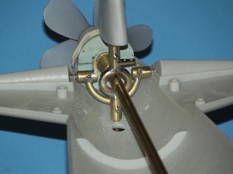
Test fitting of control yoke masters with dummy drive shaft
I fabricated the stern plane operating shaft yokes and the rudder operating shaft yokes from brass rod. Here I’m checking the yoke masters as well as an assembled propeller assembly with mock intermediate drive shaft to check for non-interference of the control surfaces through their full 35-degree travel up/down, left/right. Once all was found to operate properly, the yokes were removed, fillets built up with CA and baking soda, pickled, primed, used to make a disc type metal casting centrifugal tool.
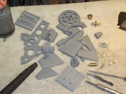
Part masters finished and primed prior to making rubber ‘tooling’ molds.
Most of the masters are now in primer gray and ready to produce the production fittings kit tooling.
The first set of fittings kit production tools were made from the relatively hard BJB Inc.,TC-5050 silicon, platinum cured, room temperature curing (RTV) rubber. The relatively ‘hard’ rubber is best suited to hold the masters when the time comes to make duplicate tools or copy masters. More on that, perhaps, at a later date.
Rubber ‘tooling’ for fittings kit parts
This shows the four two-piece production tools used for resin part production. Note that the control surface cavities have been outfitted with brass operating shaft inserts, as well as brass rod mandrels in the torpedo launcher foundation tool, and a brass pivot pin in the ‘accessories’ tool. The inserts will be partially encapsulated in the hard resin and become operating shafts, pivot pins, and cylindrical bores.
With all inserts in place I spray in some ‘Mann-200’ mold release spray, dust on some talcum powder (a ‘bubble getter’), assemble the halves of a tool, sandwich each tool between wooden strong backs, and clamp the assembly tight with rubber bands. Catalyzed resin is poured in through a single sprue hole where it is distributed to the cavities through a system of runners – displaced air is routed out of the cavities through a separate vent-channel system. I’m a master at rubber tool design.
The ‘Mann-200’ keeps the polyurethane resin from sticking to or attacking the rubber, but not completely as these tools have a 100-200 cycle life before becoming too brittle for use. Talc acts as a wick to pull resin into portions of the tools cavity that otherwise would trap and hold air pockets, which evidence on the part as pinholes.
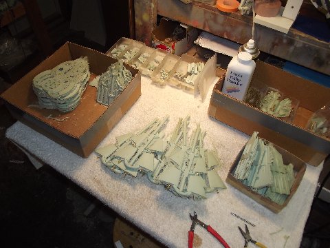
Raw resin castings (with talc powder at back of table.)
Most of the Caswell-Merriman 1:72 SKIPJACK fittings kit is fabricated from cast polyurethane plastic – some of those raw shots seen in the center of the table. I remove the individual parts from the trees, machine back the stubs, and file off most of the flash. No attempt is made to degrease the resin parts. I leave that for the customer.
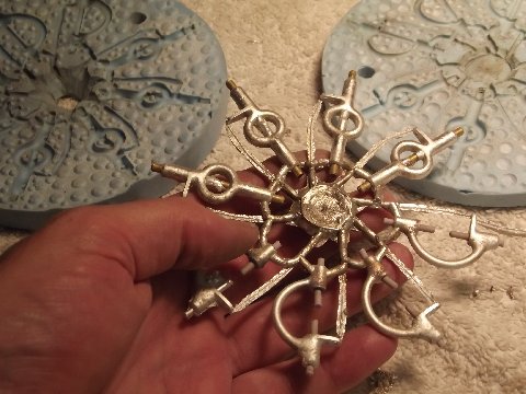
Disc mold for ‘spin casting’ of metal parts
This disc-shaped rubber tool is spun in a modified blood separation centrifuge as molten white metal (an alloy of tin and antimony) is poured in through a sprue hole at the center of rotation. Rubber mandrels set within the cavities form the bores for the stern plane and rudder operating shafts. Another virtue to the TC-5050 is its ability to handle low-melt metals that can be poured successfully at a temperature below 600-degrees.
Once the yokes are snipped away from their runners, the mandrels are pulled and each yoke is drilled and taped to receive the operating shaft retaining set-screws.
The white-metal SKIPJACK propeller – both the Moebius kit and the Caswell-Merriman R/C conversion fittings kit represent the original five-blade ‘power’ screw – starts life as a gravity poured white-metal casting, which explains the long sprue on the center propeller. Tall to take advantage of the pressure head produced when pouring the molten metal into the screw cavity of the mold: the taller the sprue, the more hydrostatic pressure at the bottom of the tool, the more inclined the metal is to seek out and fill all cavities within the tool. Also, the tall sprue acts as a header in that it serves to provide make-up material should there be a leak across the flange face of the two tool halves.
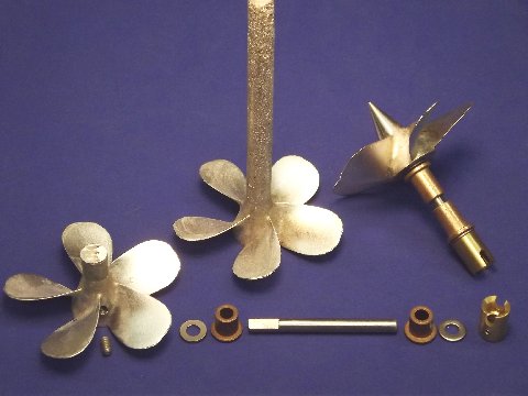
Three stages in the propeller finishing process
Shrinkage is not an issue with white-metal – which actually expands a bit during the state change from liquid to solid – the antimony expands in volume when it freezes.
To the left is a propeller casting with the excess sprue cut off on the band saw. To the right is a finished propeller whose excess sprue has been turned to the proper pointed dunce-cap shape. Note the assembled Oilite bearings and thrust washers, propeller shaft, stainless steel thrust washers, and Dumas style universal coupler. The screw is secured to the propeller shaft with a transverse 6-32 X 1/8″ SS set-screw.
Trackbacks: