
1:48 Scale Martin P4M Mercator by RCM (Robert’s/Combat Models)
Order via website: www.combatmodels.us (kit 48-020 w/ resin detail set) $59.95 plus shippingPart 2: After my initial impressions of the Combat Merc, I have decided I would just “go for it”. I gathered up as many spare parts that seemed of likely use, including a spare set of Monogram B-17 wings (for the engine nacelles and airfoil sections), a bunch of spare Monogram B-24 parts plus a pile of Monogram P-61 interior parts (I found the 20mm cannon parts from the Widow were especially nice and ideal for the nose & tail gun turrets.) I also had a spare set of True Details P-61 engine cowlings that looked good for the forward 3/4 of the Merc’s cowlings, with a bit of enhancement. But, after scouring the spare parts bins, I found I really didn’t have much that was directly applicable to the project.
What I did find was what a treasure trove the Steve Ginter book really was; without all the specs and pictures it contains, I don’t think I could have even attempted the work necessary to make the model look like a Mercator. So when I say it is indispensable, I mean it.
Example of one of the required “plugs” to stretch the fuselage to the correct length.
I found the station drawing was great for determining just where the fuselage elements were to be located. It allowed me to see exactly where I needed to lengthen the fuselage to achieve the “long & lean” look of the real deal. Turns out the kit is short about 1.5 scale feet (¾ inch) in length – but not from all in one spot. Hence, any ‘stretch’ would need to be spread across several points.
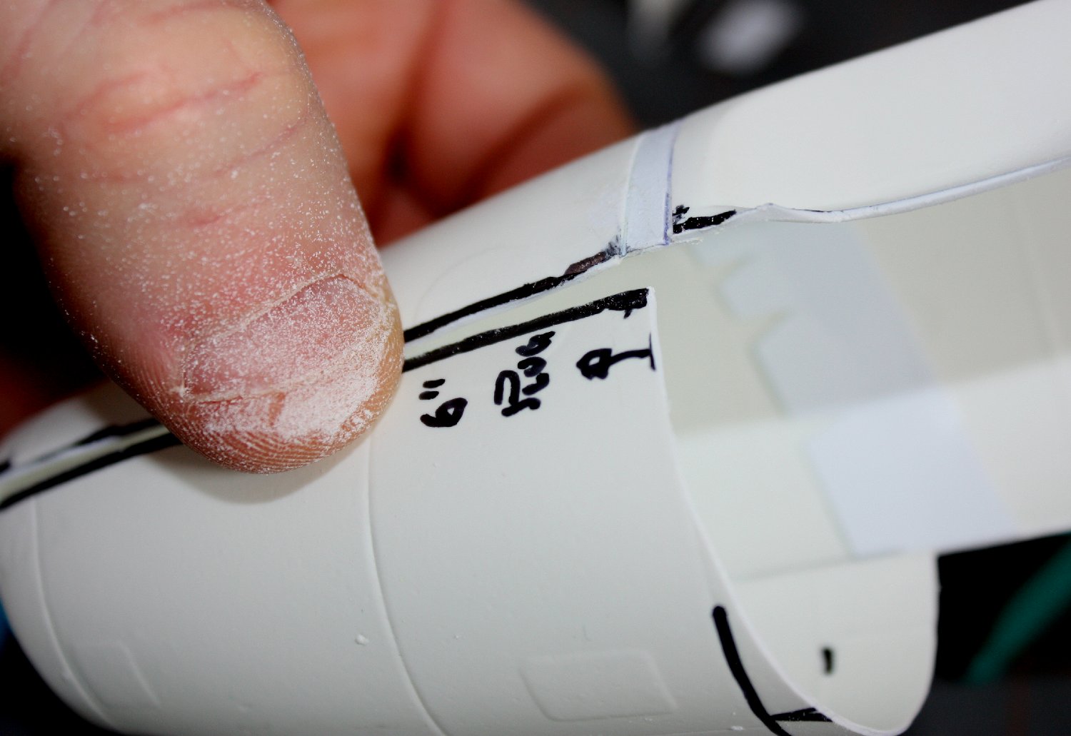
I started by cutting out the fuselage pieces. I used my standard methodology (see Vac Aircraft Modeling, Part 4) using a Sharpie pen to outline the parts before carefully scoring around and snapping each piece free. I focused on the fuselage first because of its known problems and because it would logically serve as an alignment reference for the rest of the assembly (wings, tails, etc.).
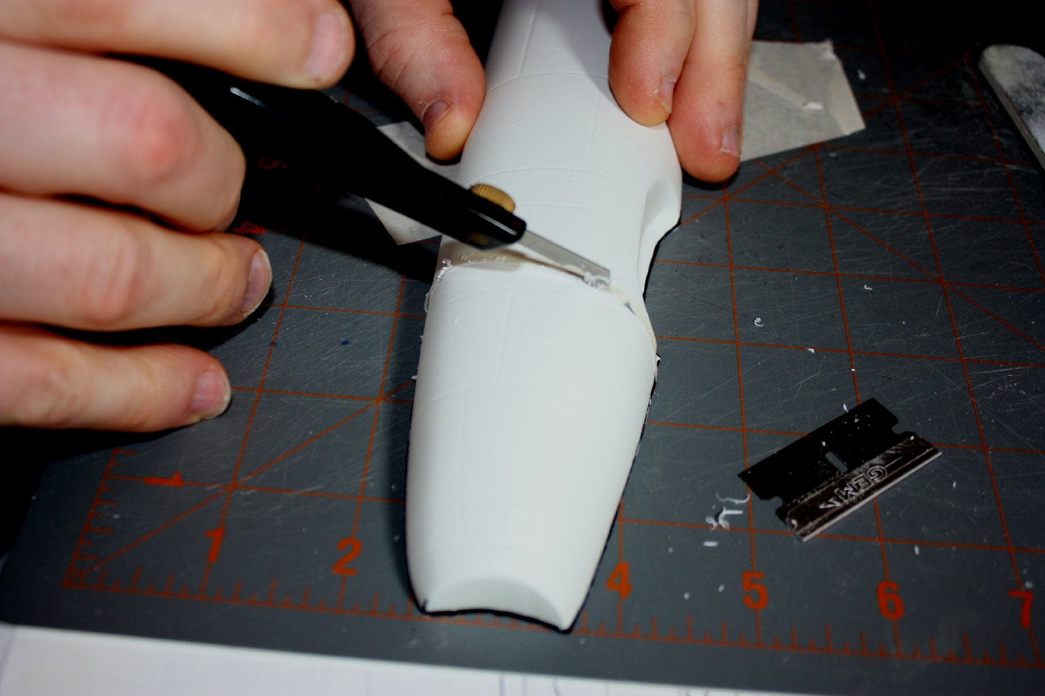
Scoring the fuselage at the separation line
Adding extra length to a fuselage can typically be done by working with an assembled fuselage (i.e, glue halves, then cut) or by doing each side separately. I chose the latter method.
So, after removing the fuselage halves, I marked where I was to cut and add ‘plugs’ to get the correct length. One was directly in front of the kit windshield location, along an angled panel line; the other was just aft of the cockpit opening. A third one would be fall just in front of the aft radome location.
To start, I used a pencil to mark the separation lines as precisely as possible on one fuselage half.
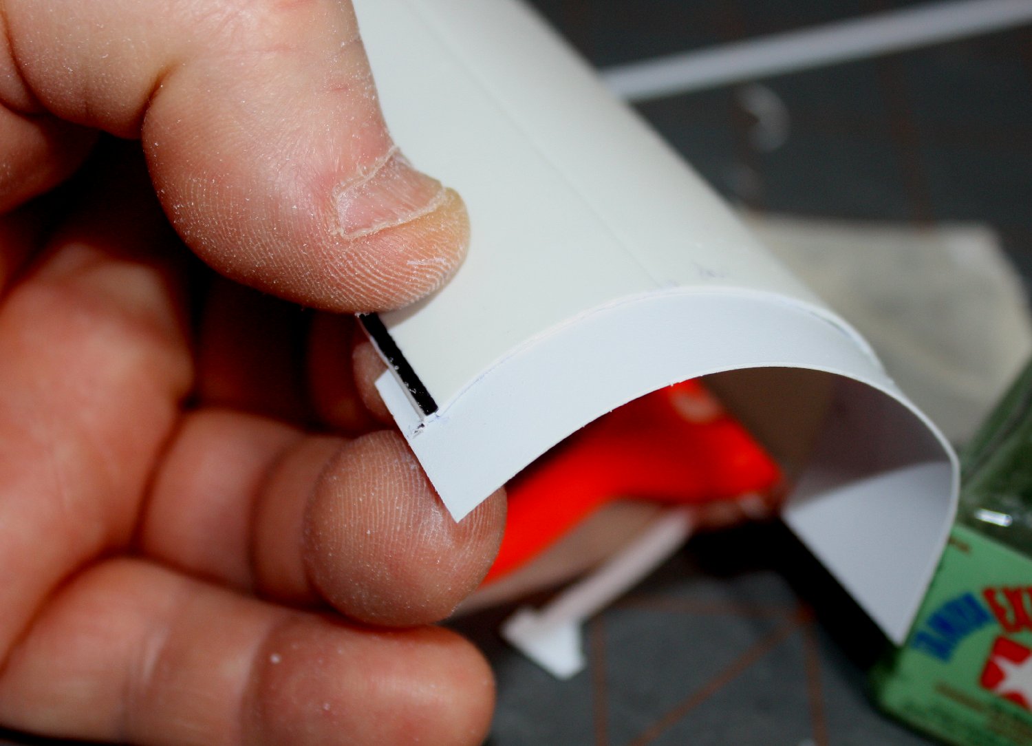
Backing strip being added to joint
I carefully scribed the marked lines so they were distinct grooves, then finished cutting through using a single edged razor blade (which accurately tracked the scribed groove.) Finally, I lightly sanded the cut edges to square them off.
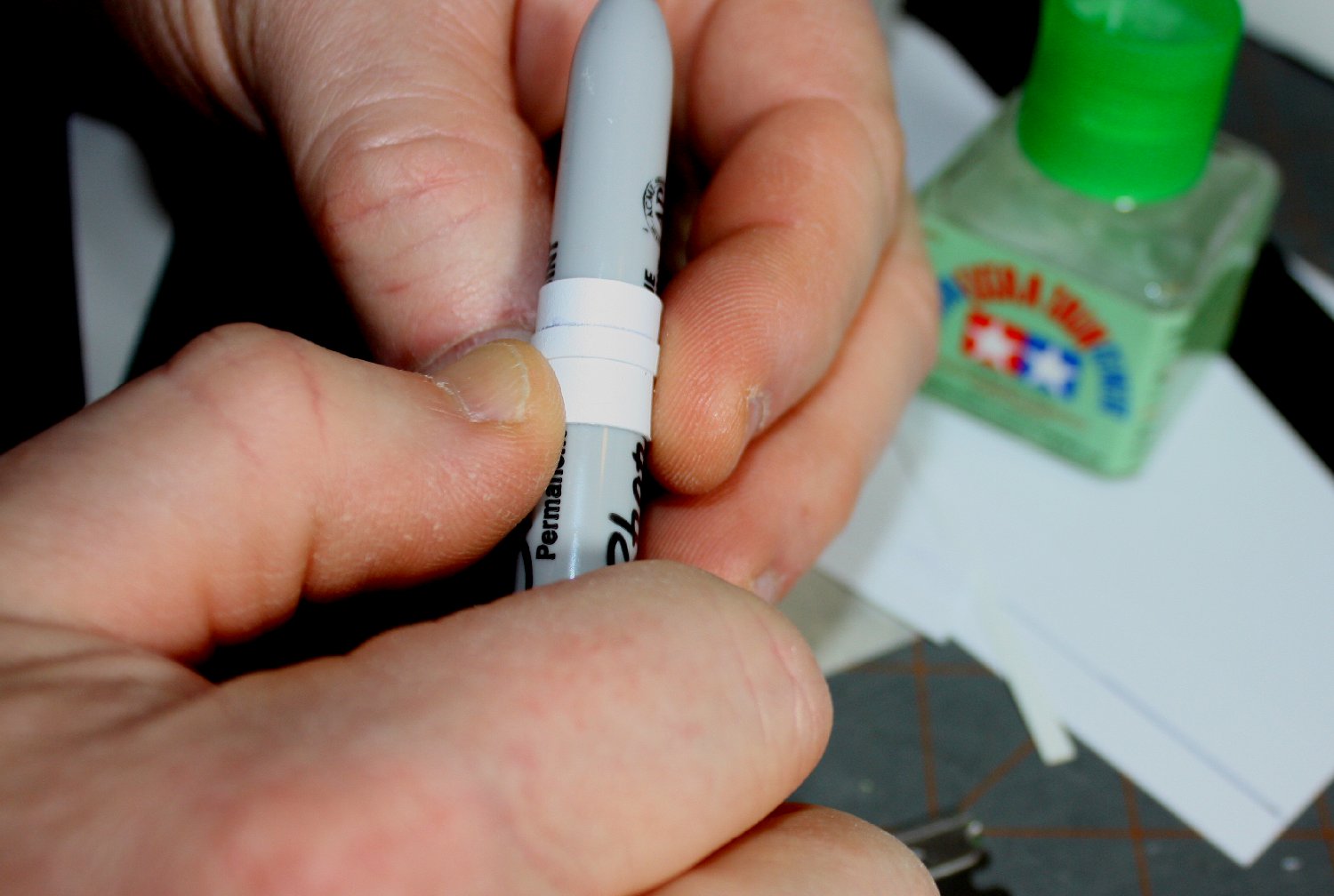
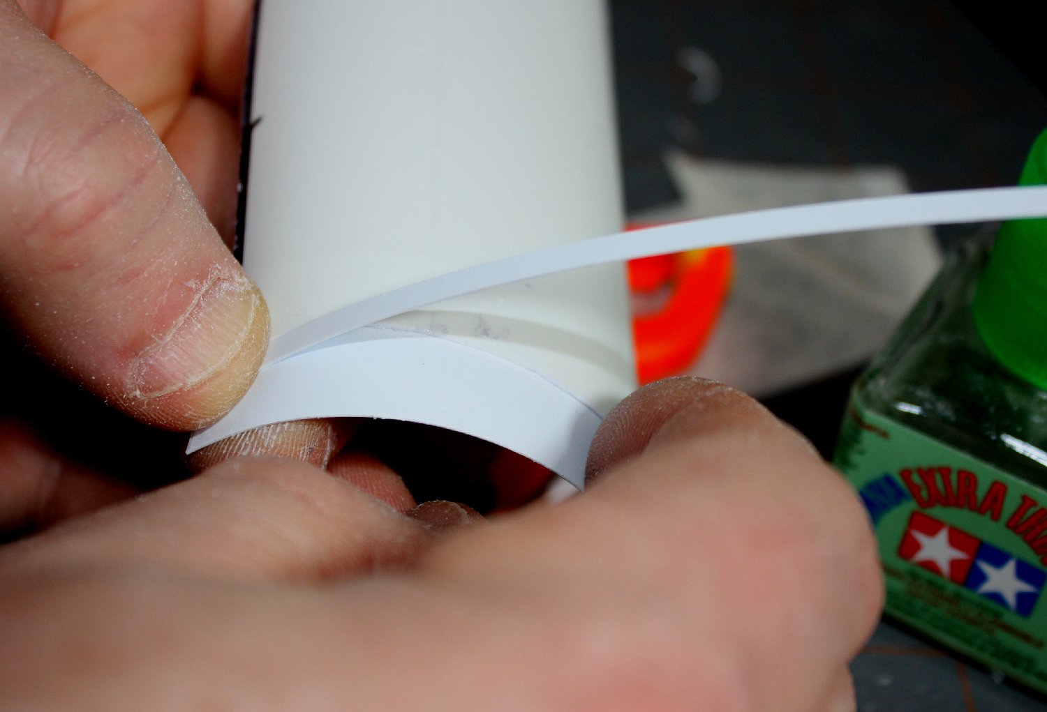
Curling the joint strips using a suitable cylinder (in this case a Sharpie pen)
I made the cuts as straight & perpendicular to the centerline as I could. Then I glued a roughly 5/8” strip of .010 sheet plastic sheet to the inside of one cut piece, using clamps to ensure a good bond. (I also tried gluing two laminated strips together before applying to the joint, but this made the strips harder to bend to the fuselage contour.)
Second strip to ‘fill the gap’ & match the fuselage thickness
I had marked the “joint” strip with a straight line for alignment reference (avoids skewing the strip.) Then I applied a constant width strip to the outside of the joint strip, which acted as a spacer for gluing the mating part in place.
A bit of pre-curling helped the plastic conform.
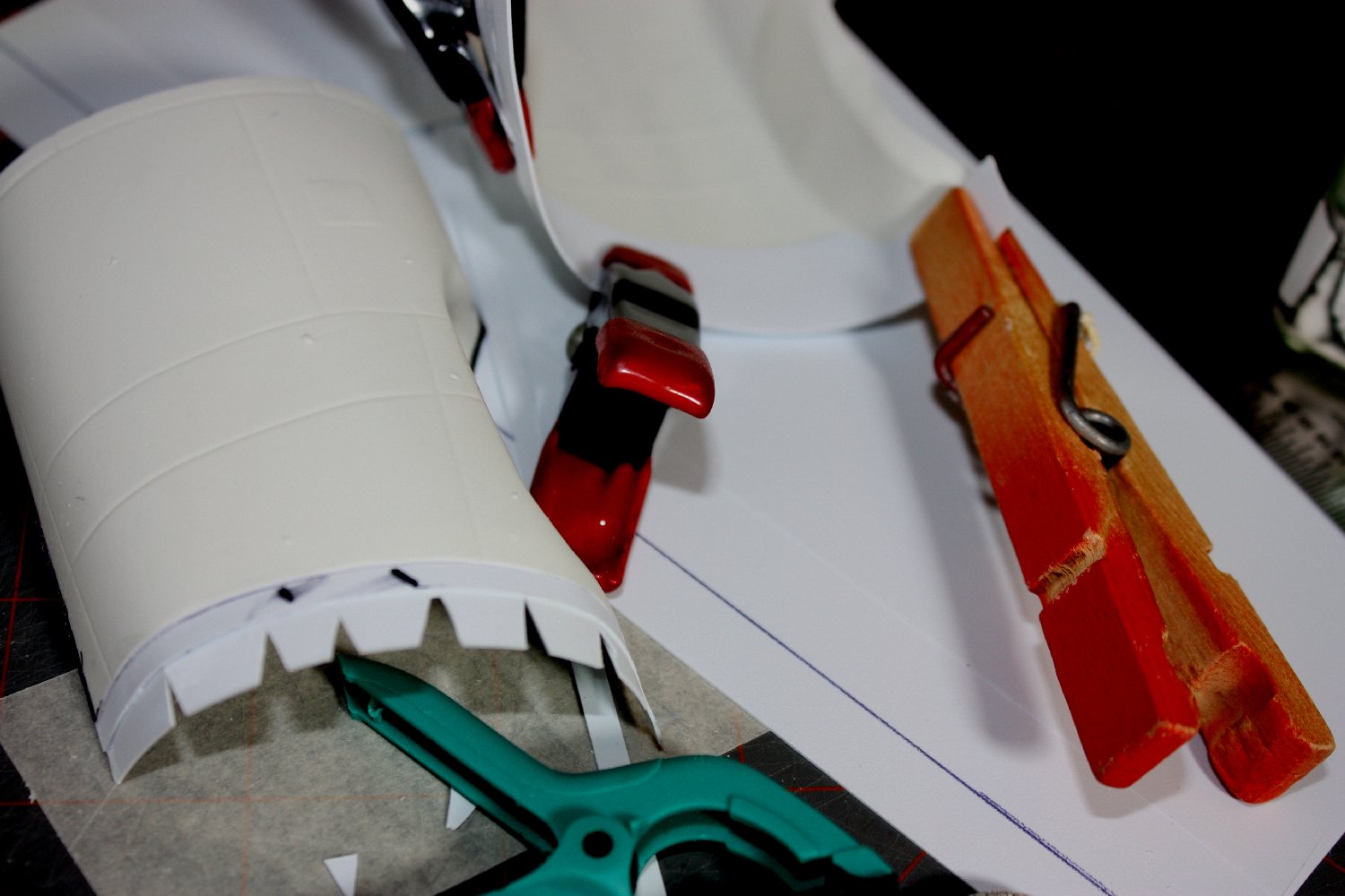
Clamping the glued joint strips; note the notched strip
Where there was a taper involved, I used a paper modeling trick. I cut V-shaped notches in the joint strip on the tapered side, which allows it be bent to a smaller cross section across the joint.
Once all the joints were set, I moved to correcting the aft fuselage contour, the cross-section of which was too oval & lacked the distinctive ‘flat-sided’ appearance of the real bird. I corrected this by brute-force flattening the aft fuselage adjacent to the tail gunner’s station after scoring a series of horizontal grooves on the inside. I then simply cut two .20 plastic ‘panels’ and glued/clamped them to the interior to brace the new contour.
My next consideration was the big, ‘floppy’ fuselage halves needed some serious internal support. I figured the best way to do this was to approximate elements of the original structure. Using the provided plans, I took the cross sections as templates for the bulkheads I’d have to make. (Methods for creating internal bulkheads is discussed in Vac Aircraft Modeling, Part 5.) Penciling in the locations of the bulkheads and floors in one fuselage half helped to define the required work. Again, the frame station drawing helps immensely; the stations are numbered in inches from the forward ‘zero’ reference at the nose, so all that is needed is to measure backwards from that point in scale inches to any desired ‘fuselage station’.
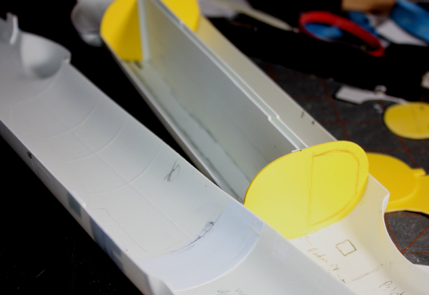
Bomb bay roof flanked by bulkheads; note marking for later bulkhead cut-out.
One thing about the Mercator is it is largely of constant cross section, so one template works for a lot of frames. It is also symmetrical side to side, so each template can be done by tracing one half and then flipping it over the center-line for both sides.
<Go to Part 1 (to be Con’t)
Hi,
Any news on this build? Thanks!
Chelsea, sadly I have placed it on the ‘shelf of doom’ awaiting my renewed attention. Regards, Robert