
A Report to the Cabal:
Here’s a brief article on how to use small gauge brass rod/wire and a purpose built assembly jig to form railing elements unique to this little submarine model. For those of you wishing to subject yourself to a Graduate course in brass work and soldering, I refer you to the work of Ron Perrott.
The Revell 1:72 Type-7C plastic model kit is nearly perfect for conversion to R/C operation. However, with all the little plastic do-dad’s on deck and hanging off the hull, care has to be taken not to damage the model during handling and operation. Styrene plastic is not GRP! [glass reinforced plastic, also known as ‘fiberglass’]
Surprisingly, the majority of the plastic parts on that kit are robust enough to lend themselves to practical operation and to ward off damage encountered during the normal handling and operation experienced by an R/C model submarine.
However, after three years of use of the first Type-7 as an R/C submarine, I have identified the deck railing pieces, ahead and behind the sail, as the parts most likely to break off – and that’s not much of a surprise as these four pieces (two opposed gun-crew railings, and two opposed railing supports) are subject to damage after experiencing even a light lateral sheering force. After breaking off one of the railings last year (a kid at one of the shows I attend grabbed the model to show his Mommy! … WTF!!), I finished the job by snapping off the other three railings just for symmetry’s sake. I was surprised – alarmed actually – at how easy that task was. Obviously I would have to make replacements out of brass wire.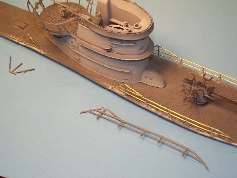
Recently, I did just that:
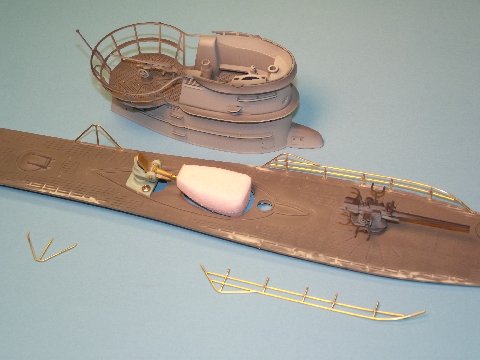
In foreground are the broken off, kit supplied, styrene plastic railings. Fine for static display – which is after all the intended use of the kit – but were found to be fragile and easily broken when subject to even a very light lateral touch. I punched .032″ holes through the broken stubs in the deck left by the original railings and, as you see here, test fit the just completed brass railings.
Being a practical R/C model, I make as many of the sub-assemblies removable as possible to ease transportation and maintenance tasks. Note the snorkel induction valve and float housed within the sail sub-assembly. 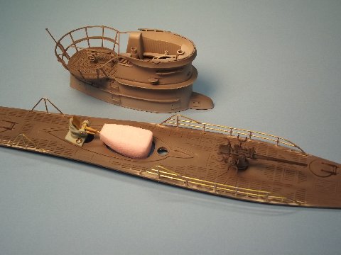 The sail attaches to the deck with the aid of embedded magnets as does the deck gun. I’ve been using this particular model as a test-mule for the semi-aspirated ballast sub-system being refined, and when ready will become an important element of a reconfigured Type-7 SubDriver (SD) we will offer to those wishing to R/C their Revell 1:72 Type-7C kit.
(Caswell-Merriman is in the process of converting our SubDrivers (SDs) over to the semi-aspirated system (SAS), from the gas type ballast sub-system. Part of the SubDriver package in the newly configured product will include the snorkel head-valve and safety float valve elements that will permit use of the SD in the SAS mode)
The key to good brass work is coming up with a means of holding the wire or sheet parts in the desired arrangement as you apply solder to make up the unions.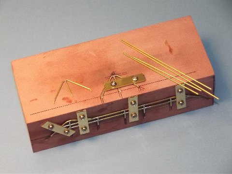 This holding fixture, or jig if intended for a specific purpose, can be made of anything that can tolerate six-hundred degree temperature, will not off-gas when heated (which can contaminate the metal-solder union) and can be machined to accommodate clamps, pins or whatever type securing fixtures you employ to hold the parts in place.
This particular jig is designed to fabricate the gun-crew railing and life-line stanchion assemblies. Note that I employ brass strip strong-backs, jacked down onto the work with machine screws. 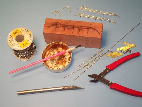 I drilled and taped holes in strategic spots on the jig to accept the 2-56 X 1/4″ SS, round head, strong-back hold-down screws.
Not shown is the 25 Watt soldering iron used to melt the 60/40 (lead-tin) solder. Other than that, this shot illustrates most of the tools and consumables used to assemble a railing part – those completed assemblies seen in background. The brass wire is .032″ in diameter – a perfect match for the plastic kit parts.
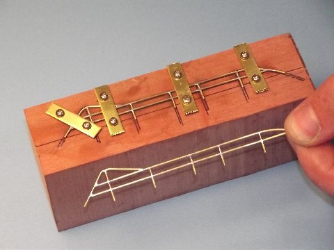
A just soldered gun-crew railing strapped down on its assembly jig. In the foreground I’m holding a filed, sanded, and ready-for-pickling railing. As you can see, the strong-backs hold down the pre-formed horizontal wire elements. The vertical elements are cut out, held in place with a modified Popsicle stick as solder is applied at the unions. Work goes very quickly with a properly designed jig – I can make an entire gun-crew railing assembly in ten minutes! Damn, I’m good!
 The new brass railing elements were removed from the jig, pickled, primed, painted and glued permanently to the 1:72 Type-7’s deck. Note that I’ve sanded the areas of the deck under the railings – there was some repair work done to the deck, filling holes and scratches, then wet sanding things down with a stiff piece of #600 sand paper. I’ll spot paint the deck with the same color used on the prepared metal railings. Once I’m done you won’t be able to see the repair.
Any fool can color-match gray! Black and white: how do you screw that up?… Watch me!
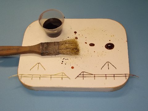 Before priming the metal parts, in order to make them receptive to the primer, I pickled the brass with ferric chloride acid. This pits the surface, which produces the mechanical ‘tooth’ to the surface of the brass and solder that will better grab the primer. Such metal conditioning is called ‘pickling’. Copper bearing metals, even with the grease and oxides rubbed off, do not stick well to primer or paint, so this sort of preparation has to be done … unless you like chipped paint on your work!
To the left are unpickled brass assemblies. To the right, pickled parts. After the acid exposure, the parts are rinsed in fresh water, dried, and are then ready for primer.
Automotive primer was applied to the pickled brass railing assemblies. The two darker assemblies atop are well etched and pitted, which is the intent of the acid pickling. The foreground railings have just been hit with the primer.
(Visit David at the Sub-Driver Forums for more submarine related modeling fun. Click HERE to see a portfolio of David’s work.)
Excellent job , big thanks. Hit upon you because the Revell railing on Type VII U-Boot is too thick and frail. However I am a beginner in soldering. Therefore questions:
– how do you get clean, unobtrusive joints?
– the railing is flat on the jig. How do you bend it (to a circle) without producing edges or without bits popping off?
– if no old stubbs are used how do yoyu secure the railing onto the deck?
Yor answer is much appreciated!
Thanks :Andy, Switzerland.